Quick Links:
Zen and Art Home
Disclaimer
Errata Parts
and Parts Vendors Truck Sales
Service
and Repairs
Engine Fuel Hydraulics Radiator and
Cooling Air
System Brakes
Wheels Tires Electrical
and Batteries
Transmission
Clutch Axles Hubs Body Air Conditioning Tools Safety
Body
Body
rust, in my mind, is very much like cancer. To perform
effective treatment requires both surgery and
chemotherapy. Chemo without the surgery may succeed, but
you are not assured the best chance of success. I had my
truck repainted 3 times in 15 years and each time we attacked
the rust. Each time the body guys were not aggressive
enough in cutting out the bad material. The rust has to
be fully contained down to base metal and then a replacement
part must be welded in and bondo-ed to produce a pleasing and
durable result. Surrounding metal should be given
chemotherapy as well to prevent the rust from coming back
Windshield
mounts seem to breed rust. If you end up replacing the
windshield, be ready for the rust at the bottom. If you
travel long enough, you will attract a large rock.
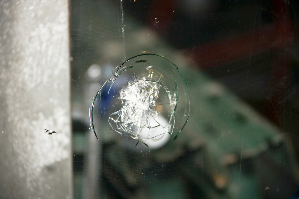
This
gem sounded like a rifle shot when it hit the window. It
was thrown by a dump truck that was many hundreds of yards in
front of us. The rock was about the size of a hardball.
The good news is that mog windshields are flat glass and they can be cut by a competent glass shop. Personally speaking, having replaced mine with tinted glass due to the desert heat, the regular glass is a better all-around choice due to the impact on night driving. If you are not going to drive at night, then tinted glass is a better choice if you live in the desert.
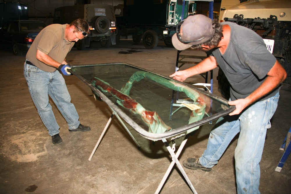
Rob Pickering and his helper Edwin put the gasket on the windshield before installing it on my 1300. Replacing the windshield is a 2-3 man job and does require some technique and a few tricks.
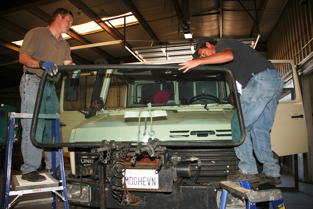
Rob and Edwin are preparing to "rope in" the windshield.
Frame Lift to Allow Mil-surplus tires
It had been 6 or so years since I have purchased new rubber for my 1300. In that time, the price of tires has more than doubled!! So, after our extended trip to Montana, my inspection of the tires showed that new tires were required, and soon. I priced the Michelin XM-47 tires that we had run with great success, and they were more than $1,000 a tire. While at MogFest, I saw that Kevin Strain had obtained a lift kit for the 1300 and was running military surplus 395/85R20 tires on his rig. This was interesting since these surplus tires were available with 90% tread at a cost of only $150/tire (shipping was extra). I got the tires from the same vendor that Kevin used, Berg General on the east coast. I am told that there are several places to get these tires, you should check in your area to see if you can avoid the big shipping charges. These are heavy duty tires and are rated at 11,000 pounds per tire at 100 psi cold. To put this in perspective, the whole truck only weighs about 14,000 pounds, wet, with camper and gear.
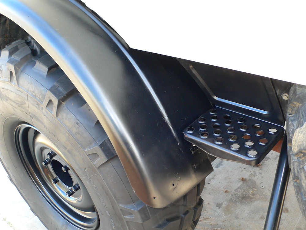
But, these surplus tires were bigger than the XMs (if that is possible) and because of their increased size, they rubbed on the front fenders on full-left-lock turns. The rubbing produced a fearful sound and was at risk of bending the fenders as well as damaging the tire.
Because of Kevin's research, I found out that there is an implement lift for the 1300. The full lift kit consists of some cast iron "pucks" that sit on top of the coil springs and some brackets and bolts used to extend the shocks. I ordered the parts and once the full compliment of parts arrived, we started the installation effort.
Like most things, it was more involved, complex and time consuming than expected. The documentation provided by Mercedes was not very helpful and in the end, it was the help and advice of the Unimog network of owners that saved the day. Special thanks to Pete Lembesis and Sean Philyaw for getting me the information I needed to complete this effort.
In principle, the task seemed easy enough: raise the frame of the truck (not THAT easy when the rig is 14,000 pounds), and undo the coil spring retaining bolts. Then, the puck and puck plates are installed along with longer bolts. Then, the shock extension brackets are installed. Sadly, this was not sufficient to prevent the tires from rubbing on the fender. My email exchanges with Pete told me that I also had to move the front fender and top step to fully complete the job.
The photos below are what we did.
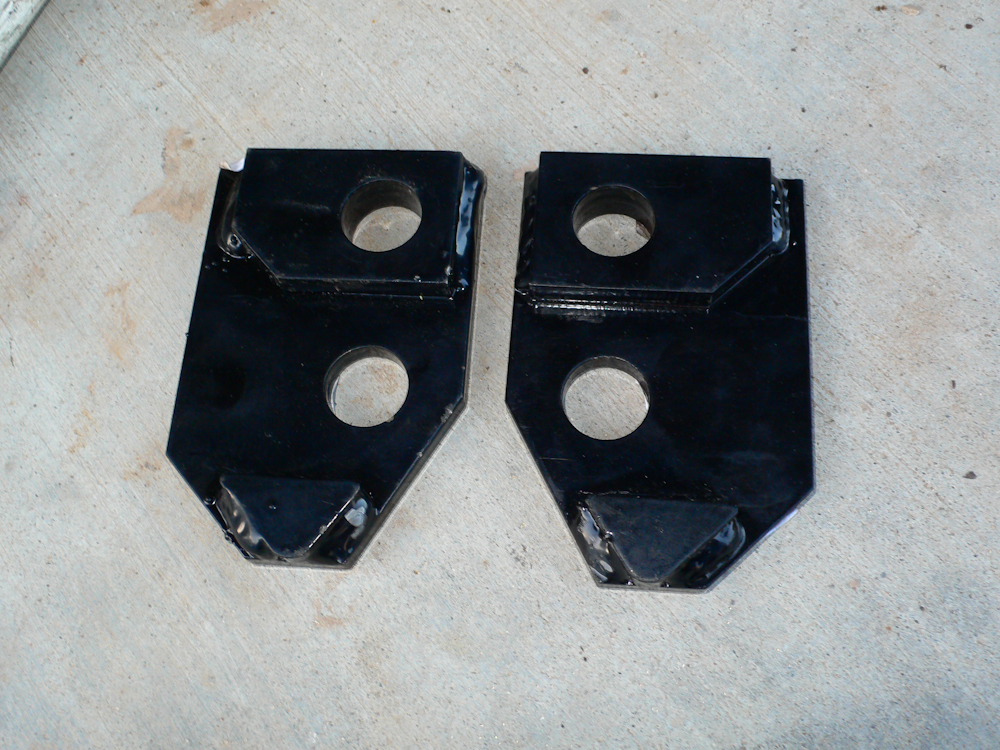
The shock extensions were only intended for the front!! 4 pairs of brackets were sent in the kit, but the brackets do not fit on the rear. This was a mystery, and in the end, I will fabricate a set of extensions for the rear so the truck is symmetrical in articulation. The photo above shows the mirror-image brackets that are used to extend the shocks. The brackets fit around the existing shock mounting brackets on the front axle with the triangle brace facing down. A detailed photo of the installation is shown lower on this page.
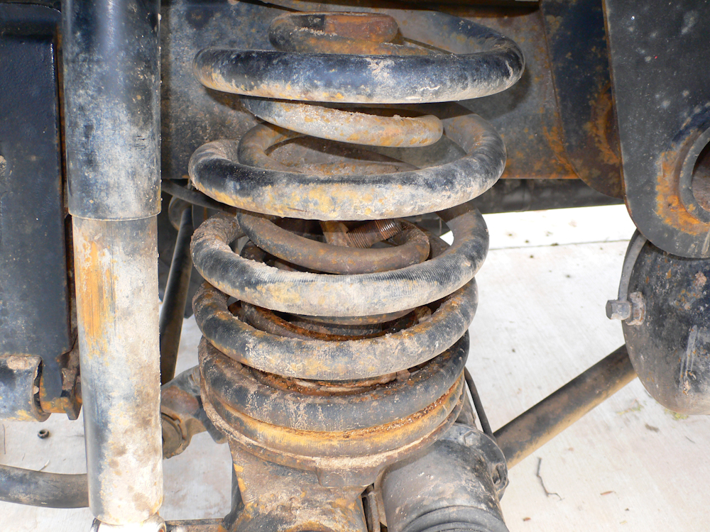
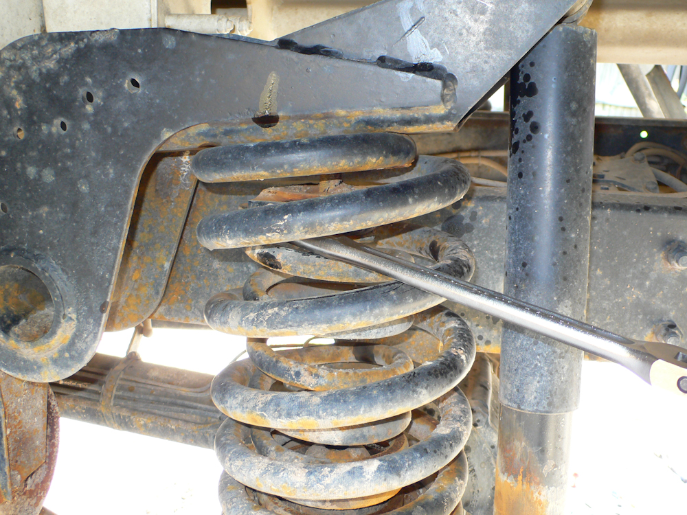
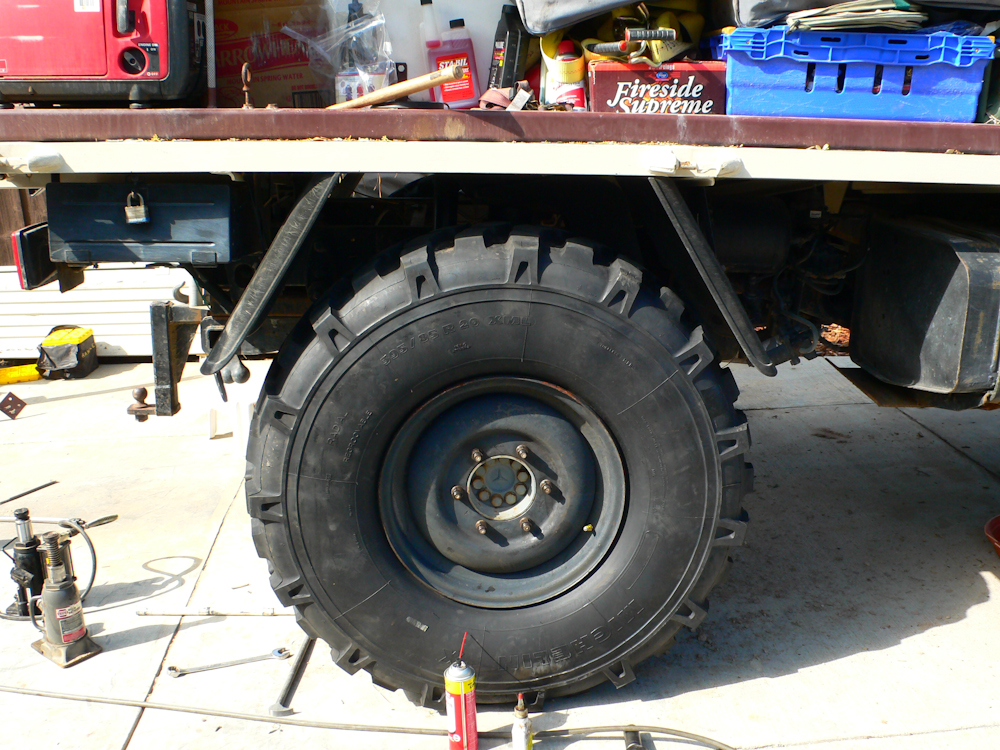
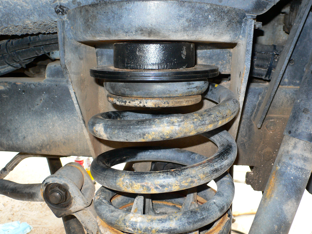
We started on the rear by raising the frame, removing the tires and lowering the axle assembly. Then the attachment bolts that hold the coils in place were removed. In the photo above, you can see the overload springs inside the main coil and the loosened bolt visible between the inner coils.
We discovered mid-way into the process that we also had to undo the sway bar to get sufficient droop on the axle to allow the springs to come off.
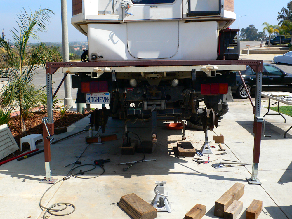
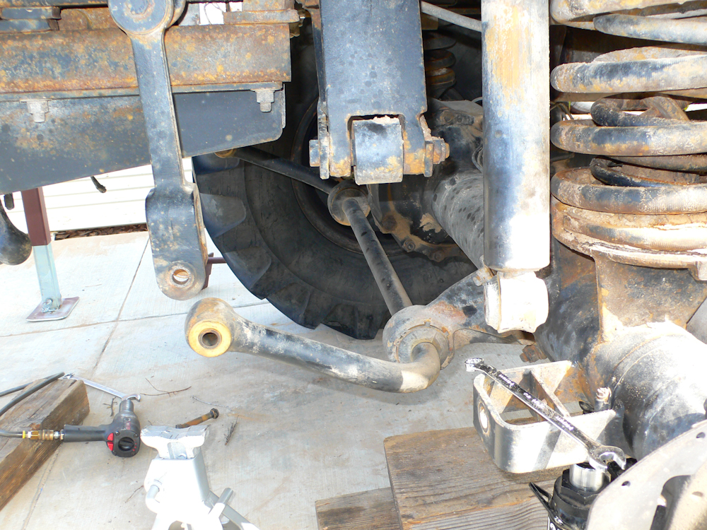
To get the job done, we had to remove both rear tires at once to provide sufficient droop and eliminate the skew in the axle that made reattachment of the springs impossible. In the photo above, you can see the support jacks that were originally designed to support the camper and frame if removal were required. This setup had sufficient strength and lift capabilities to support the entire rear of the truck, including camper.
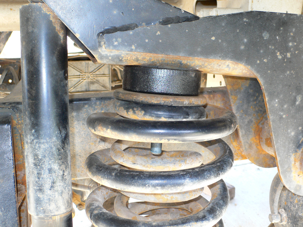
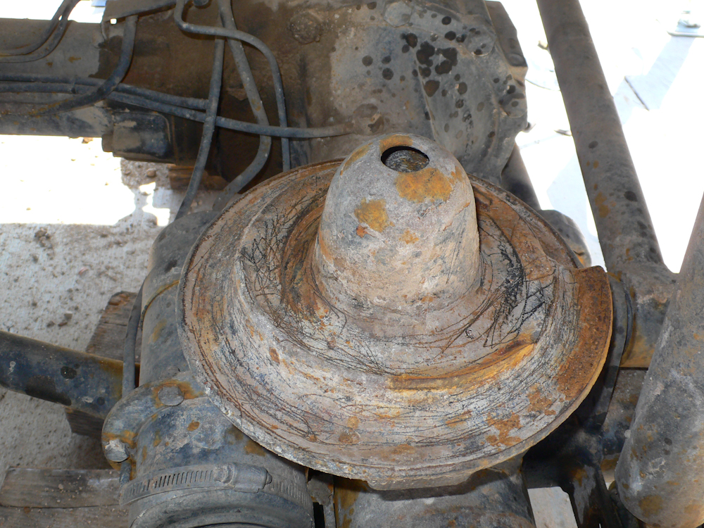
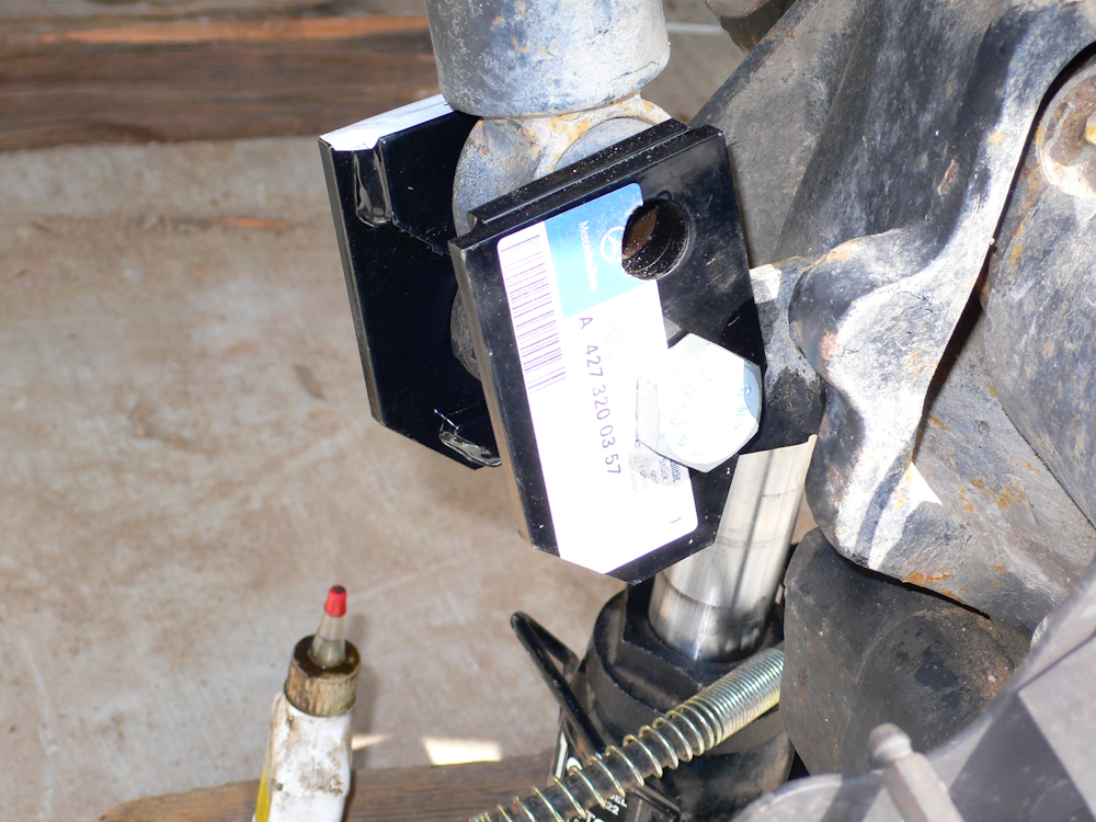
Test installation of the puck. In the final installation, we put the head of the bolt on the bottom and the nut on the top. The first side was pretty easy after the lifting setup was handled.
On the driver's side rear, the spring retainer plate was mis-installed requiring prying and pounding to get it loose.
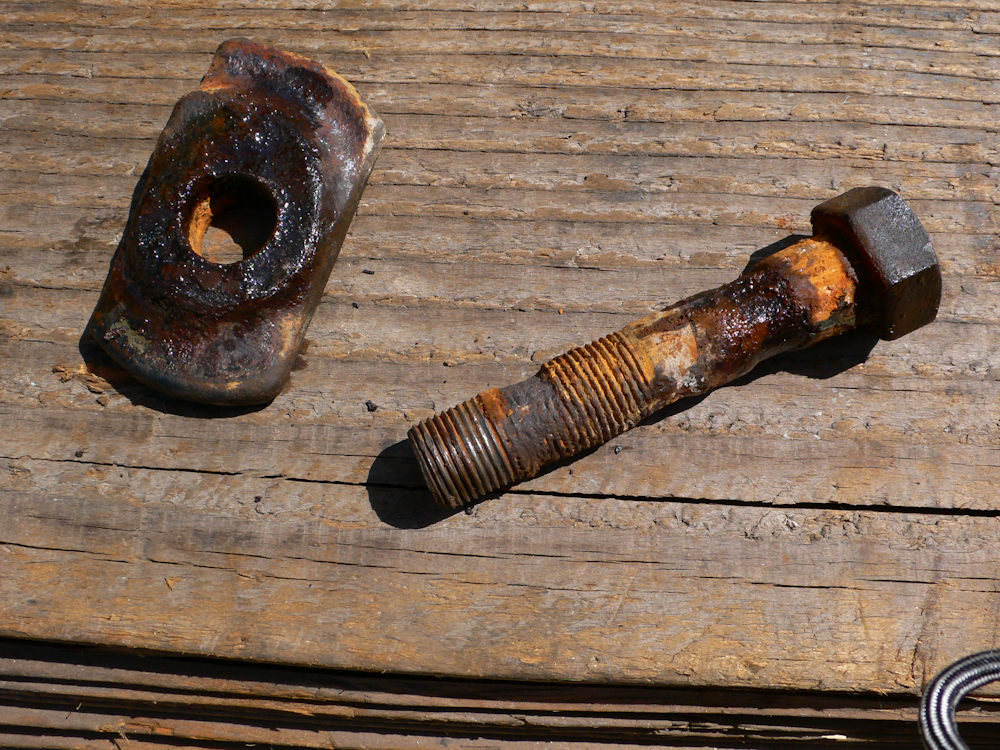
Because it was installed incorrectly, it allowed things to move around and wear the bolts. As you can see, the bolt is well past the end of its useful service life. Due to the corrosion, getting the nut off the bolt was really tough.
Probably due to the incorrect installation, the spring had bottomed out enough times to erode the mount.
The bottom of the assembly was fully caked in nasty salt mud from our last trip to Mexico. After much scraping and wire brushing, it was clean enough to reassemble.
Completed rear axle with tires mounted. The jacks were removed and used for the front.
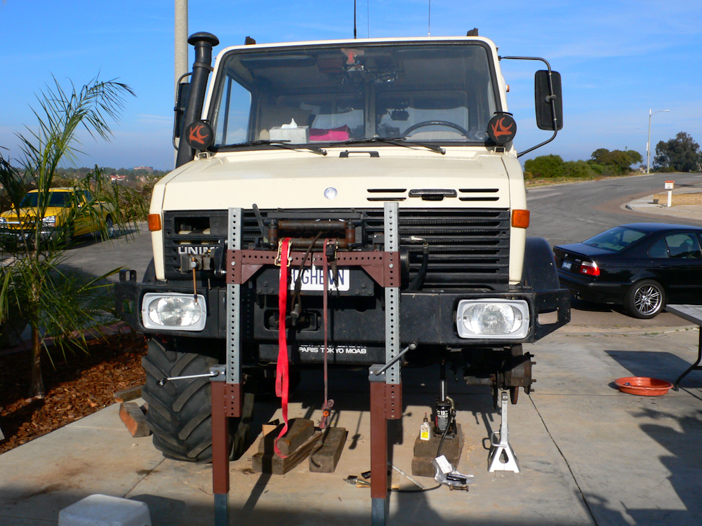
We repositioned the truck and put the jacks under the front winch. The front is the heavy end of the truck, but the jacks are rated at 5,000 pounds each so we had plenty of safety margin. That said, it was still a bit scary since we had to lift the frame more than 18 inches to allow sufficient axle droop.
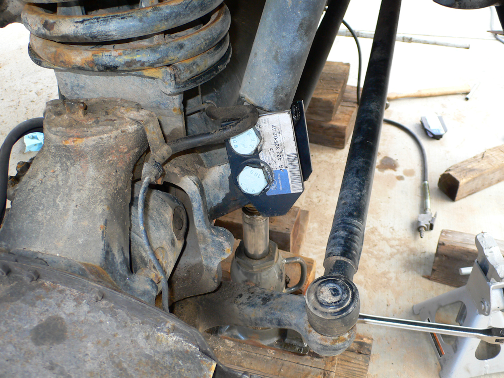
The installation of the shock extension brackets was "non-intuitive" to say the least. Thanks to Pete for his photos and advice. Not visible in this photo is the spacer sleeve that fits over the lower bolt between the brackets.
The front bolts were tough to get off, but in the end we did what was required.
The kit had 4 plates, but there was no obvious place to use them in the rear so I put both on the front. Also, I had to drill out the plates as the bolts supplied were much smaller than the hole in the puck and retainer plate. It was easier to expand the hole in the plate than consider the whole assembly sliding around.
Not shown in photos is the brake modulator extension. On the 1300, connected to the rear drive shaft tube is a rod that "senses" the load on the truck. That information is used to modulate the braking pressures delivered to the calipers. Given the lift of the truck, the assembly would "think" that the truck is unloaded and therefore deliver poor braking performance. Upon inspection, it was seen that I could extend the limits of the rod without replacing or modifying the assembly. The original length of the rod was 235mm and I extended it to 250mm to account for the lift in the suspension. This extension resulted in good braking performance, on par with the XM-47 tires and an un-lifted frame.
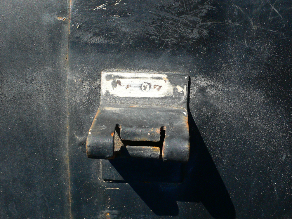
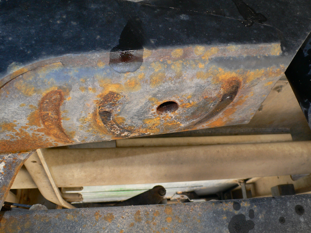
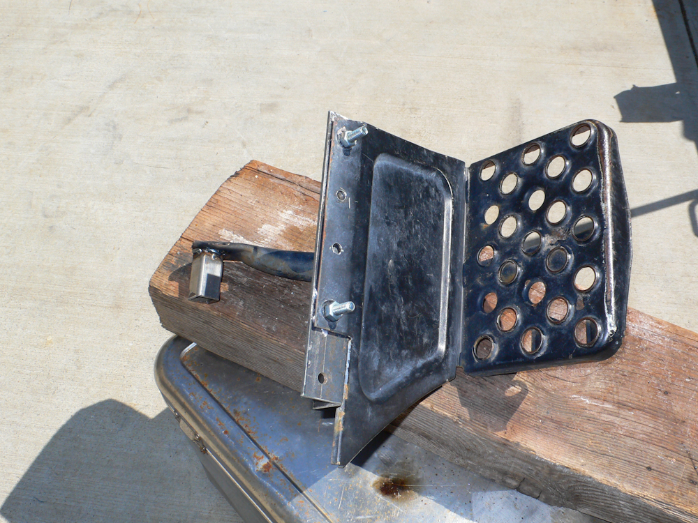
Now for the real hassle. To prevent the tires from rubbing, the fender needed to be pulled aft by about 2 inches. To do this, the bracket that attaches the fender to the top step needed to be moved. Additionally, the step needed to be moved as well. The first action was to remove the bracket which required drilling out the spot welds and then re-welding the bracket in the new, desired location. Above, the position of the spot welds can be seen.
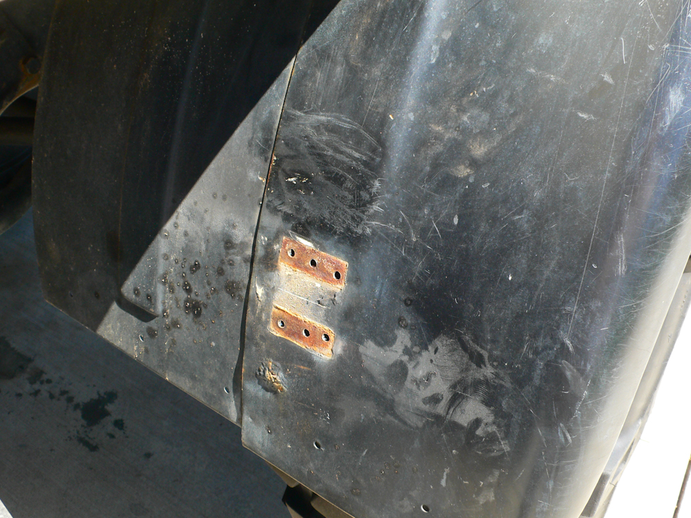
After some drilling and prying, the bracket came off. Note the big bubble of rust under the bracket location. This rust pocket is right beneath where I want to mount the bracket.
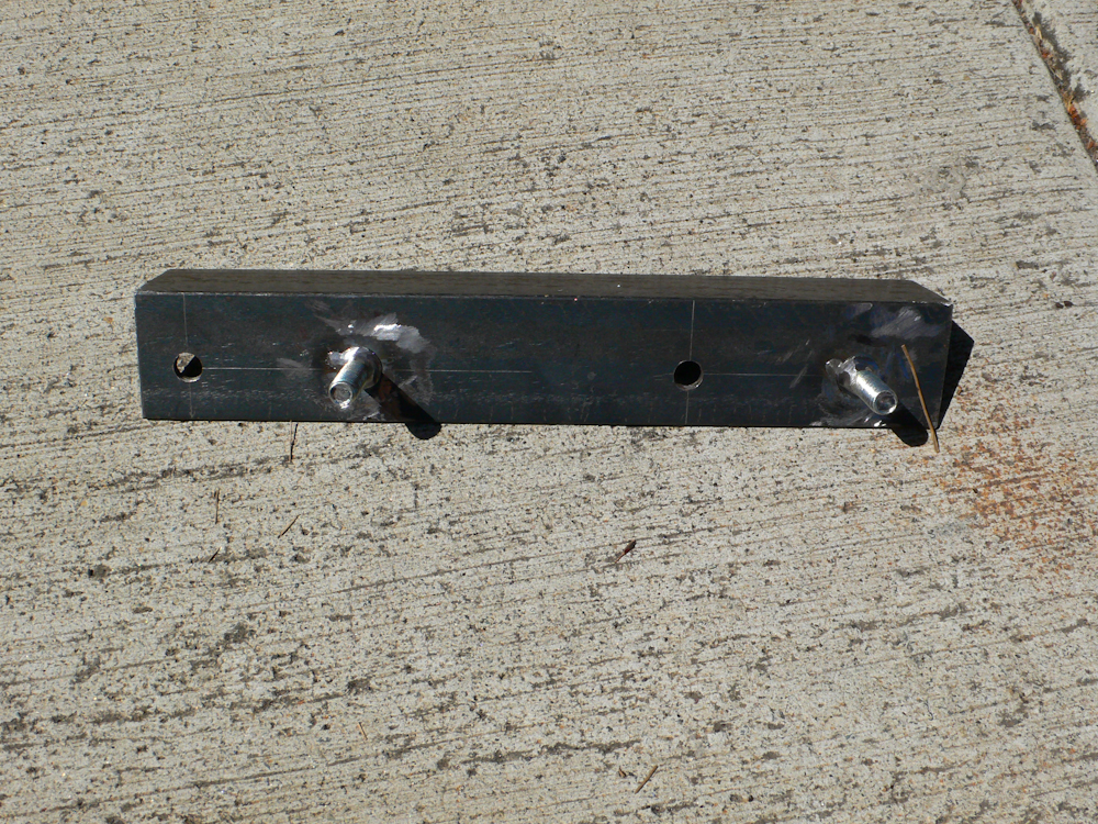
To move the step, a new attachment bracket is needed. Based on Pete's design suggestions, I fabricated one out of a couple of bolts and some 1.5" angle.
A spacer for the rear mounting support is needed as well. I made mine from 1x1 square tubing. In the photo above, the bracket can be seen attached to the step.
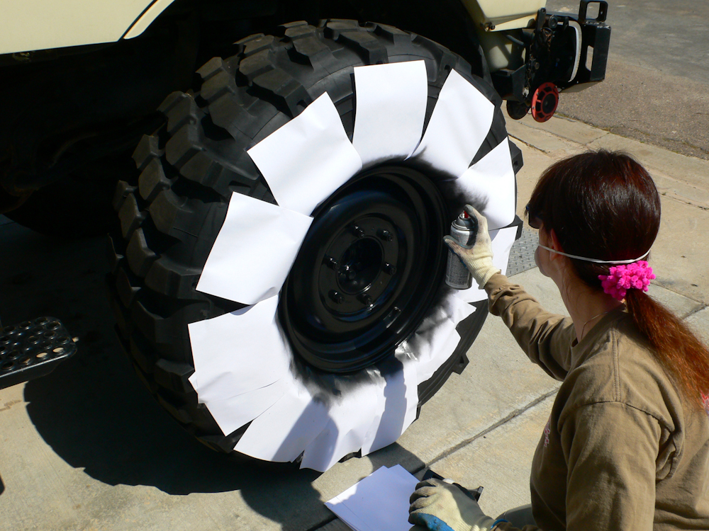
The wheels we were using were "new" so we needed to paint them. Above, Kathleen masks the wheels and spray paints them with medium gloss black.
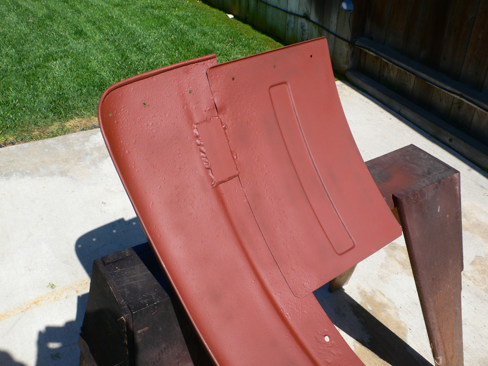
When I attempted to weld on the fender, the rust caused me to burn holes in the material. In the end, I had to put a backup plate on the inside of the fender to cover my damage. The real solution is to get a new fender.
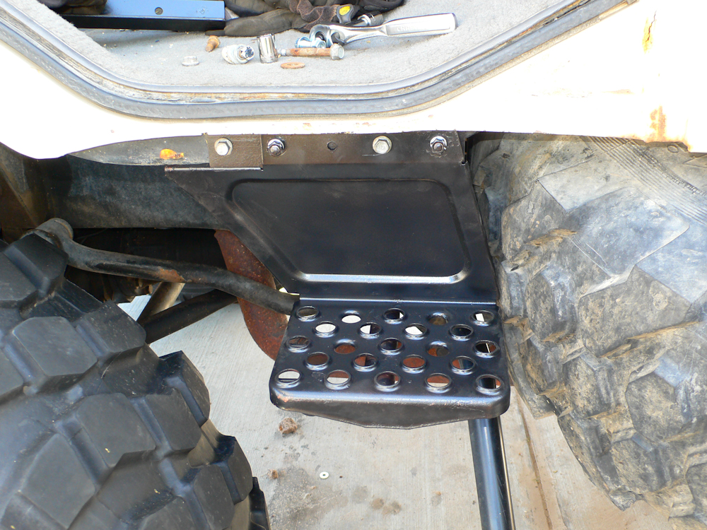
The top step is mounted on the cab. Note that the bracket allowed movement of the step to the rear by about 2". The good news is that it was not that hard to make. The bad news is that there is now an interference with the spare tire that will require removal of the step if I have a flat.
The finished installation.
Observations on Use
After the installation was completed, we did a 'wheeling trip to the El Paso mountains. There were some moderately hard trails there, but the trails did have sections that resulted in large amounts of body roll. There were no interferences between the tires and fenders. So, to that end, we have deemed the installations a success.
As for the tires, they work pretty well. They do buzz a bit, but all off-road tires buzz. They seem to have pretty good road manners and did handle off road acceptably well. It should be noted that these tires "want" 10" rims and the Unimog rims are 11". As such, these tires will have a tendency to debead if operated at low air pressures. When we were in the El Paso mountains, I was running at 25 psi. I had no debeads, but was still concerned.
I have been running the tires at 36 psi cold and have had good results. On the way back from El Paso, I ran the pressure up to 60 psi as a test. The truck "hopped" while we drove. We progressively lowered the pressure until the hopping went away and ended up at 38 psi cold. We still got occasional hopping, so on our return from Tucson, we lowered the pressure again to 36 psi and the tires seemed better mannered. Since the installation, we have logged about 1200 miles on these tires and so far, I am pretty happy. These tires carried us 20,000 miles to the Arctic Ocean in Alaska and back. They were down on the wear bars by then, but they performed well.
One of
the downsides of running the bigger tires as that they do not
fit in the stock spare tire holder. So another approach
needed to be developed.
The problem with big tires is that they are heavy. And really big tires are really heavy. The basic tire for my 1300L is the 14.5R20 which is a big tire. But, to allow deep sand operation, even bigger tires are needed. For the past 5 years I have been running Michelin XM-47s. These work great off road, but the problem is that once the camper was installed, there is no place to stow a dead tire in the event of a flat. I use the stock spare tire mount in my truck and it easily stores the 14.5R20s. But, the XMs are way too wide to be stored in that rack. So, if a flat occurs, using the 14.5s for a spare is fine, but without a place to stow the dead tire, I would have to abandon it. And, unless I was willing to de-mount the tire, I would have to abandon the rim as well.This would be both costly and wasteful. Before the camper was installed, the dead tire would just be hoisted into the bed using the canopy hoops and a come-along. But, after the camper was mounted, there is no place to store the dead tire.
I built a very strong steel basket for the back of the truck to store extra cargo when the camper is mounted. The initial concept was to use the storage for my cooler and fire wood. The basket is plenty robust enough to hold the tire, but the problem is how do you get an awkward, 300 pound tire into the basket? Particularly if you are in rough terrain and the truck is off-camber.
The plan was to design a crane that would be easy to assemble and disassemble. The geometry of the back of the truck and basket is such that to make this work and provide reliable support for the 300+ pound tire and wheel would require a pretty beefy frame. The frame will need to connect to the camper to provide the necessary bracing and to offset the "moments" generated by the weight of the tire. Due to these requirements, it was clear that the crane could only be used when the camper was down and in the travel configuration. Stated differently, if you want to raise the camper, the crane frame would have to be detached. Also, the XMs are big enough that when they are in the basket, you cannot lower the tailgate and therefore access to the inside of the camper is blocked. So, this means that the dead tire would have to be unloaded before access to the camper would be possible and then loaded again the following morning. Not ideal, but potentially practical if the crane assembly and disassembly were easy enough.
After thinking about all the constraints, I came up with a design that would be both strong and easy to manipulate. The only real constraint was that due to the weight of the tire, the rear tailgate would have to be up and locked before lifting could occur. The plan was to have 2 inserts that would be placed into the existing bed sides. Attached to the inserts would be U joints connected to the crane masts, with one mast for each side meeting in an "A". The masts would be bolted together with a plate that would provide both the lifting point and a connection to the roof rack that would provide the offsetting force to the load. The connection is a simple tension member and would be stowed with bolts onto the existing roof rack. The masts would stow on top of the bed sides by having them rest on a saddle. The plate would also be stowed on the rack.
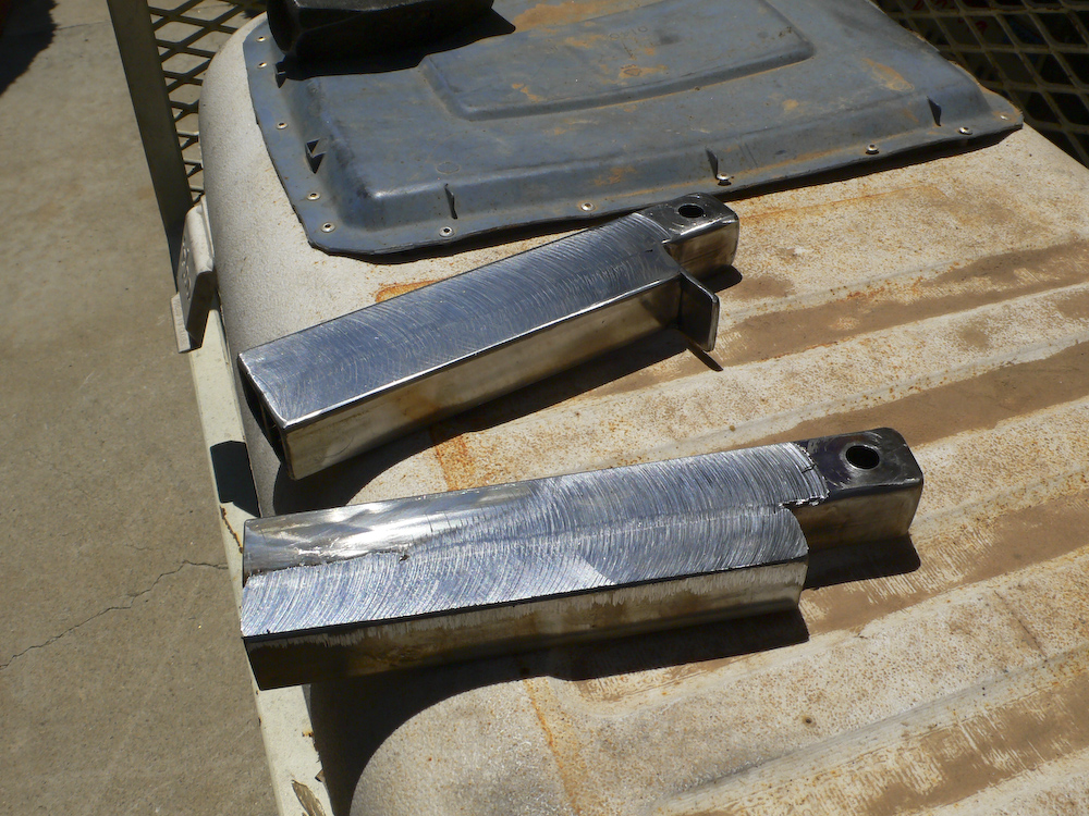
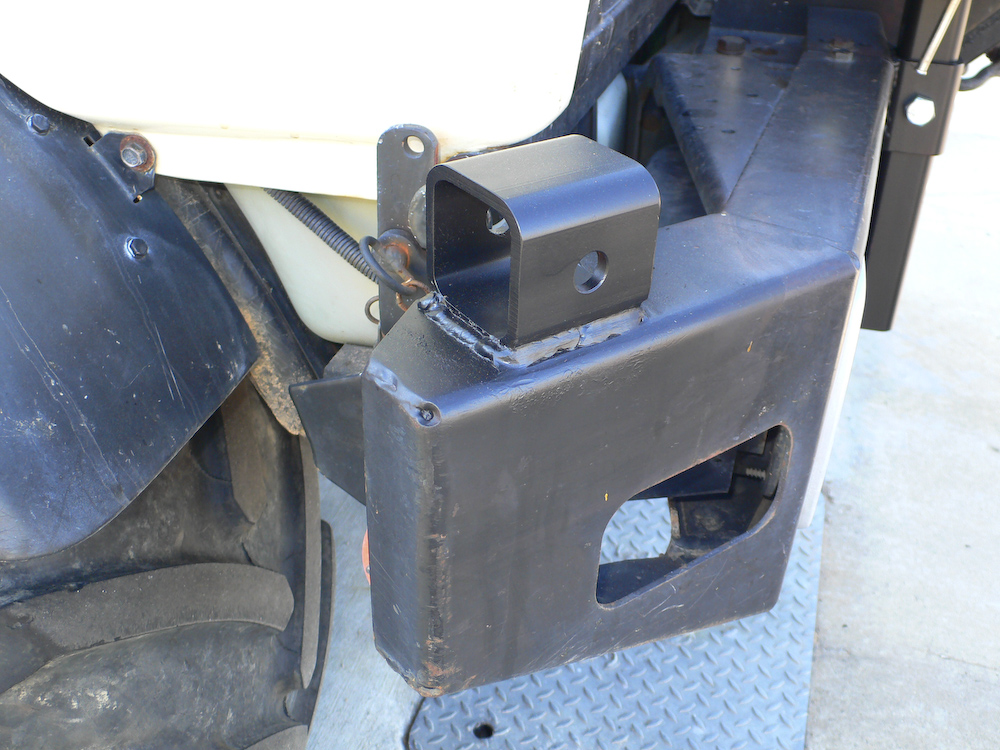
The inserts that will connect the masts to the bed sides. The back one is completed, the front one lacks the top tab. Note that the faces of the inserts were milled to achieve the correct thickness to provide a mild interference fit. Thanks to Mark Mitchell for assisting me in this process.
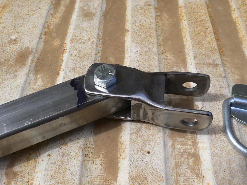
The U joints were made out of a short section of 3mm wall square tubing and 4 pre-fabricated, pre-punched "gate tabs".
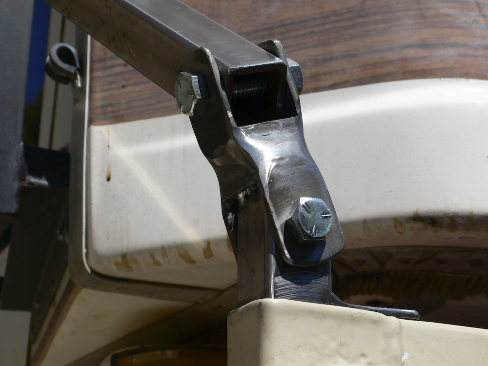
The masts were about 1.54 meters of 3mm x 25mm square tubing. Above, you can see that the insert has been pounded into the bed side.
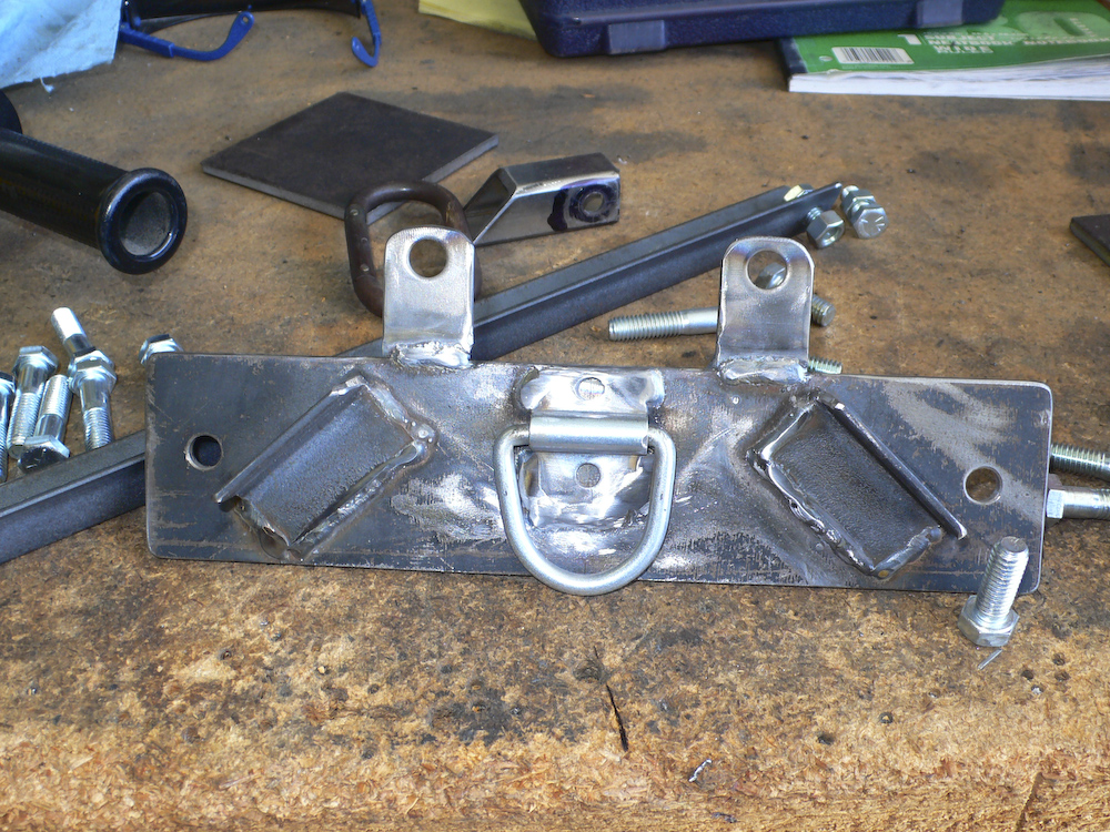
The top connection plate was made from some scrap 1/4" plate that Mark had in his shop. The angle was welded prevent it from rotating during the mounting process. The large D ring was added to provide a strong and flexible lift point.
Above, you can see the tension member has been added. This member is 1x1 angle and connects to the mounting frame of the roof rack.
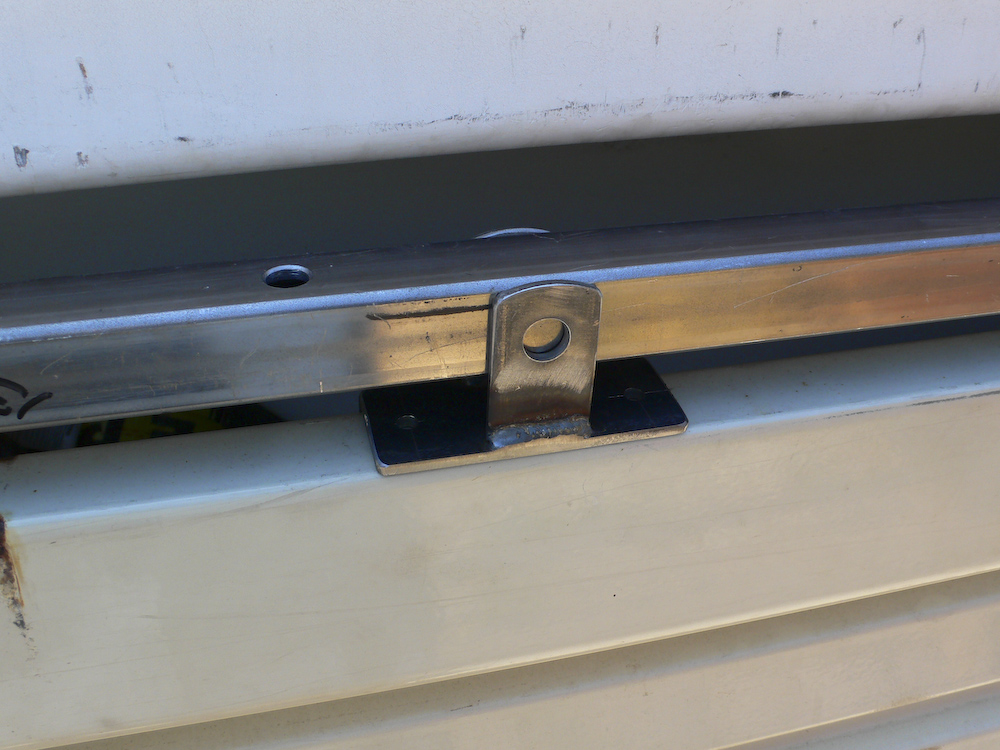
The mounting saddles will fit on the bed sides. Above, the holes in the mast have not yet been drilled and it is being fitted. The saddles will be connected to the bed with 3/16" pop rivets. Ball-lock pins will hold the mast in place.
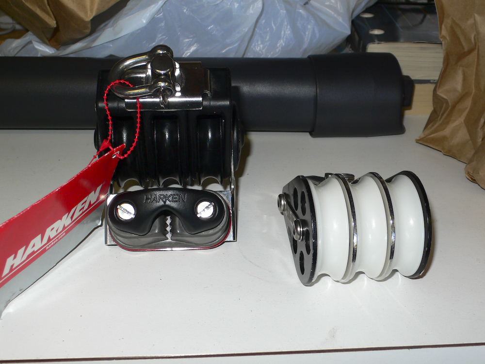
The real issue is how you lift the tire. As you may recall, due to Mark's suggestion for the camper, I used marine grade components in the truck. The same place, West Marine, came to my rescue this time. Mark uses a simple 6:1 block and tackle to lift cargo into his truck. The idea was sound, so I planned to use the same. But, these components were not cheap!! The 2 items above plus some low-stretch rope was $285. The photo above was taken before I assembled the block. One of the trick features of this block is that it has a cam cleat that locks the rope so you do not have to pull on the line all the time. This cam assembly is at the bottom of the left component.
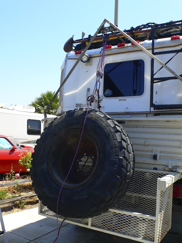
First lift test. I used a regular 14.5R20 tire as ballast reasoning that if it could lift that easily, it could also lift a somewhat bulkier XM-47. One of my requirements was that I could do this alone, without assistance. I ran that test several times, and even lifted the tire with one hand.
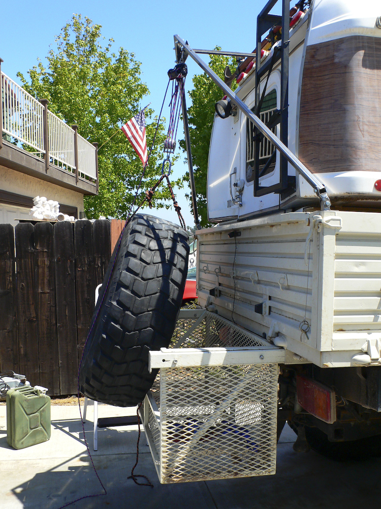
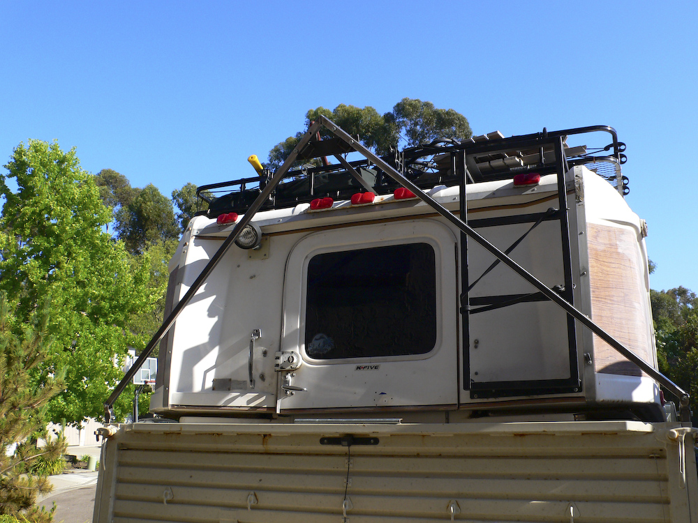
I designed the crane so the lift point would be over the center of the basket. That way, the tire would naturally swing into the basket and the swing would be blocked by the rear tail gate. To remove the tire, you have to swing it out over the edge of the basket. But, if you have extra line on the lifting strap, it becomes easy.
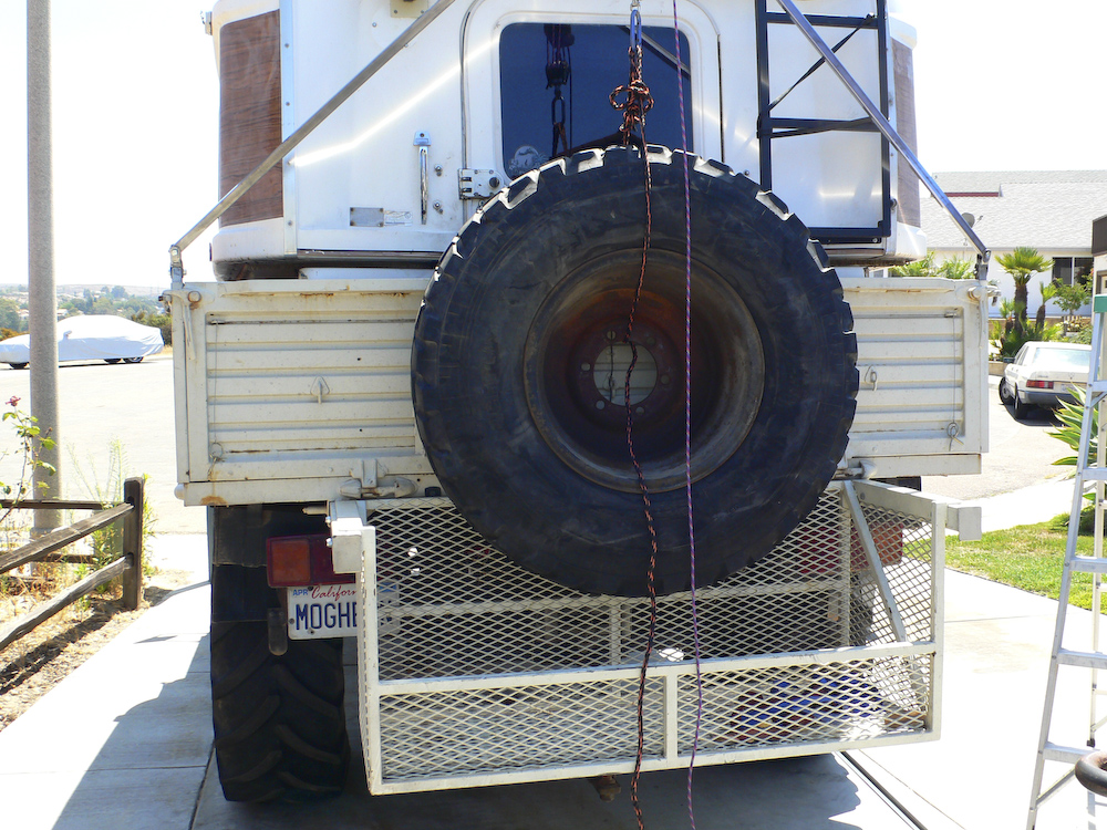
Maximum lift height is constrained by the minimum length of the block assembly. Look at the reflection in the mirror and you can see that the components are quite close to each other.
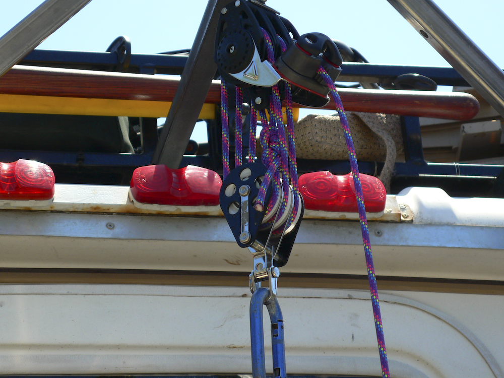
A close-up of the block assembly. Note the rope in the cam cleat. Also, you can see the tension member just to the left of center in the photo. It is connected to the roof rack mounting frame. Once this test was complete, the parts were disassembled so they could be primed and painted. Once the paint is dry, the saddles will be affixed and the whole crane will be reassembled "for real".
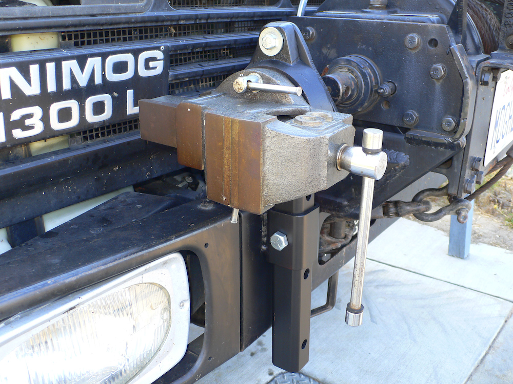
To address the need for a holding fixture for repairs, I decided to use a spare vice that I had in my garage. I went to the steel store and bought some trailer hitch components and some 3/8" steel plate. Mark was kind enough to lend me his cutting torch and drill some holes in the plate and tubing. The outer sleeve was then welded to the front of the bumper with careful attention to allowing the bumper fascia to be removed if required. In the current location, the vice is usable as-is, but another mount is needed to allow use for normal operations.
I took another small section of the 2 1/2" 1/4" wall tubing and welded it to the end of the front bumper. This allows me to easily move the vice to the alternate location. Plus, since the vice is on normal trailer hitch tubing, it can be plugged into another vehicle if required.
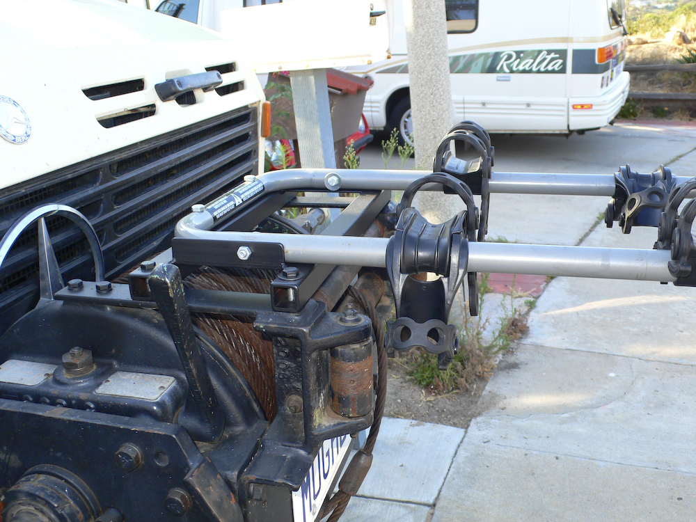
To provide an easy and secure mount for mountain bikes, I cannibalized Kathleen's Yakima rack that she used (once) on her 330 BMW. Then, I welded up a small mounting point that hooks to the front winch. The gray tubing is easily removable by taking out 4 bolts. The balance of the setup is more permanently attached and was not intended to be removed.
This was a ton of work to do these 3 mounts. But, we now have the peace of mind that should we need them, we will have them available. We have used the bike rack already on a beach cruise. I am totally OK if the other 2 devices are never used. Particularly the crane since its use implies one of the XM-47s has gone south and changing one of those is a ton of hot, dirty work.
Air Conditioning
Very few mogs have factory a/c. Current mogs can be purchased with a/c, but the newer trucks are quite pricey. But the good news is that for 1300 mogs (and all the SBU models) it is possible to add a/c. Red Dot makes a unit that can fit on the roof and can be installed on the gun hatch without too much bloodshed. I had such a unit installed on my 1017A Mercedes truck and it works fine.
I had a
Green Dot European unit installed on my 1300. This unit
was a tight fit under the hood and required some modest
re-work on the fuel filter mounting to allow everything to
fit. This unit also had custom plastic ducts that fit
under the dash resulting in a factory-installed look.
The good news is that the mog has extra belt races to power
things like the air compressor and hydraulics. The air
compressor race was co-opted during our installation.
Generally speaking the a/c units work well and produce sufficient cooling EXCEPT with an un-tinted windshield heading into the sun late in the day when the outside ambient temperature is 110+. The large flat glass of the mog windshield turns the cabin into a solar oven when it shines through. And there is nothing like thinking "which is better 95 degrees with the window up or 110 with the windows down (but a breeze)".
These a/c units, like all a/c units must have the coolant lever verified and refilled as required. Running it "dry" risks frying the compressor.
The
photos below show the installation process for the Green Dot
a/c unit on my 1300.
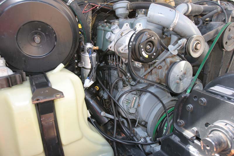
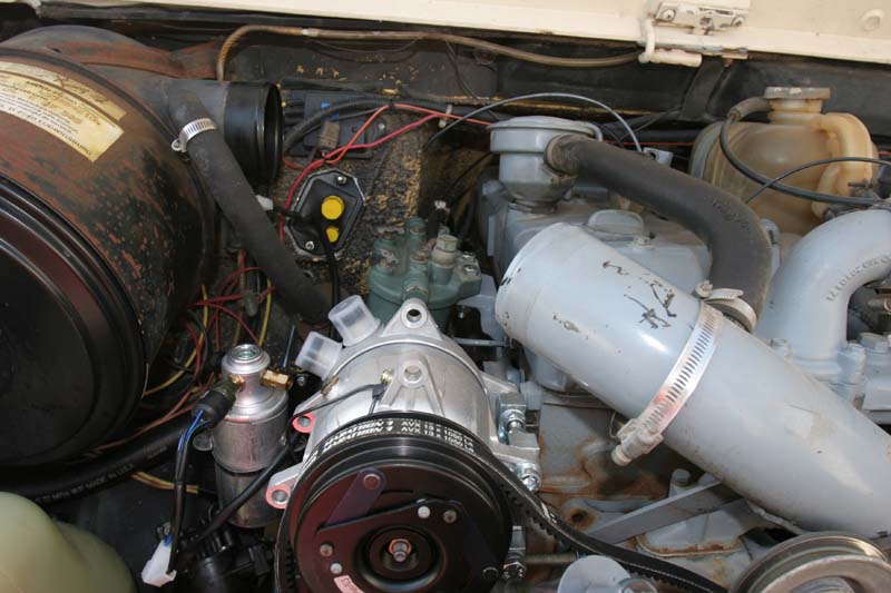
A/C compressor and new water pump pulley installed. Kai had to re-fabricate the bracket for the fuel filters. The dual black belts on the engine pulley are for the hydraulic pump for the winch.
Colored plugs on firewall are pass-throughs for the refrigerant to the heat exchanger on the other side of the firewall.
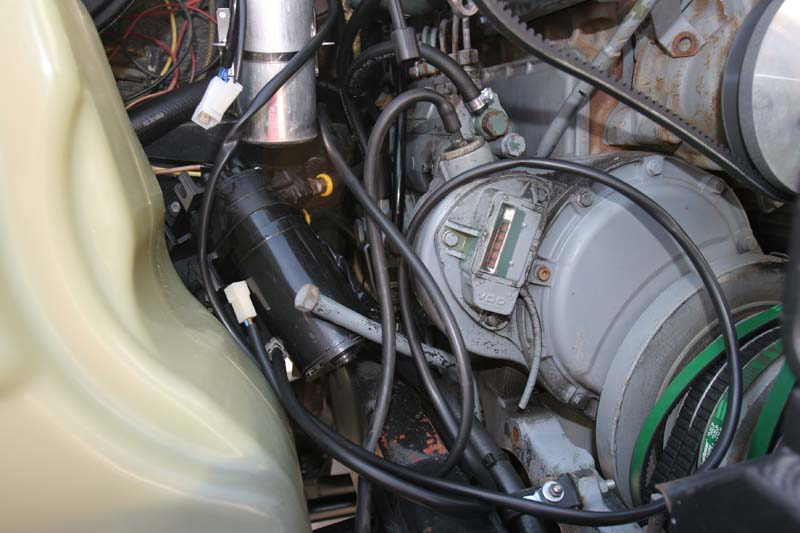
The mounting for the pre-luber had to be moved as well to allow sufficient room for the a/c components.
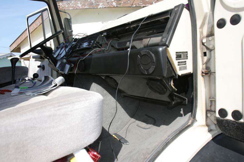
Air ducts were mounted under the dash. Note the vent ports and the cooling coils in the foot well.
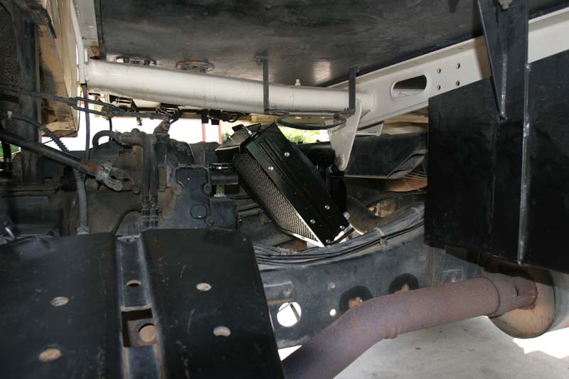
New fan and condenser
mounted underneath the frame.
The air conditioner unit was a great choice. It worked well for the balance of the time that I owned the vehicle (2005-2010) and to the best of my knowledge is still working.
The body lift, too, was the correct decision. This allowed the use of low cost, ex-mil surplus tires that greatly reduced the cost of operation of the truck.Quick Links:
Zen and Art Home
Disclaimer
Errata Parts and
Parts Vendors Truck Sales
Service
and Repairs
Engine Fuel Hydraulics Radiator and
Cooling Air
System Brakes
Wheels Tires Electrical
and Batteries