
At
the conclusion of Part 13 of this blog, we took the "mostly completed"
rig to Baja with some of the local moggers. We had a great time
and the truck performed as expected. There were no problems with
any of the additions that we installed prior to the trip. You can
see photos of the Baja trip by clickking here.
Once we got back into the U.S. and the dust and mud was cleaned from the vehicle, we continued prosecuting our set of actions for the truck. The photos below show what we did as part of these actions.
I
did not take a bunch of "work in progress" photo, but the photo above
shows the finished product. The objective was to provide a
convenient and robust way to store and mount our flat panel display for
travel and use. We fabricated a frame that allows the panel to be
folded up for travel and then rotated down for use. The top tray
provides a spot to put the laptop and hard drives that store the
movies. The mount does not interfere with the movement of the top
and still provided optimum viewing height.
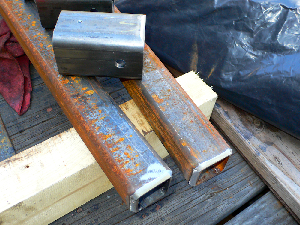
From
the LCD mount, we moved on to completion of the cargo box mounts for
the rear of the truck. Like the other mounts, these will be
constructed of 2x2 1/4" wall square tubing. The completed
assembly will plug into trailer hitch reciever to allow the assembly to
be removed if required. Above, you can see the reciever mount has
been cut, drilled and tapped in preparation for welding. Also
note that the 1/4 wall tube has been chamfered to insure full
penetration of the welds for strength.
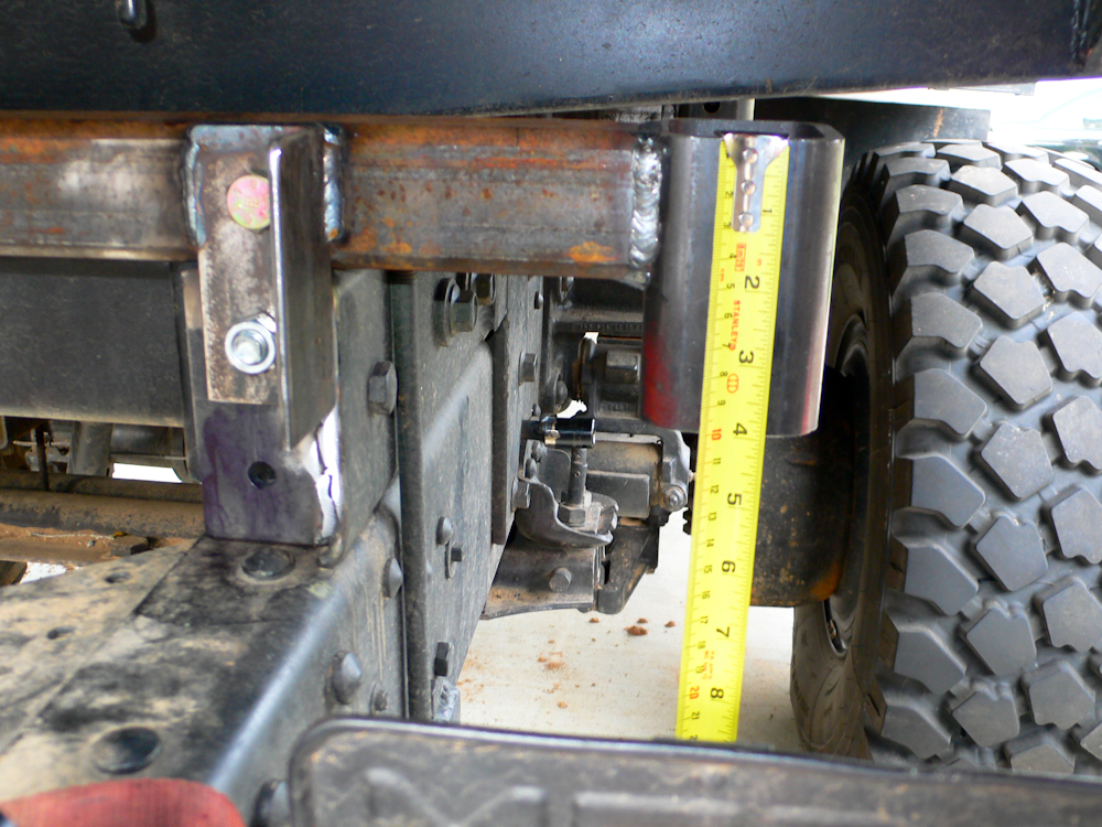
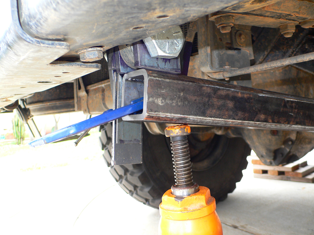
Once
the mounting bars were fabricated, they were test installed to confirm
measurements of the balance of the components. The rear bar is
attached to a cap plate welded onto the end of the upper frame rail.
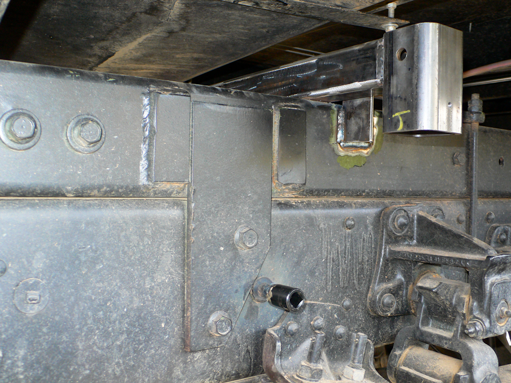
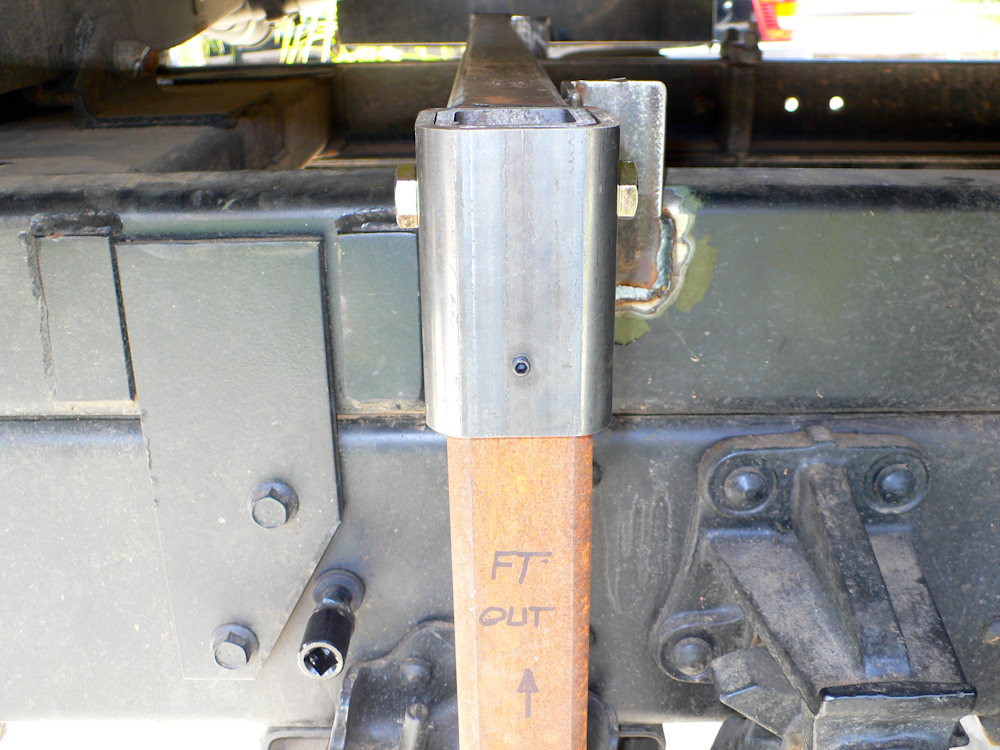
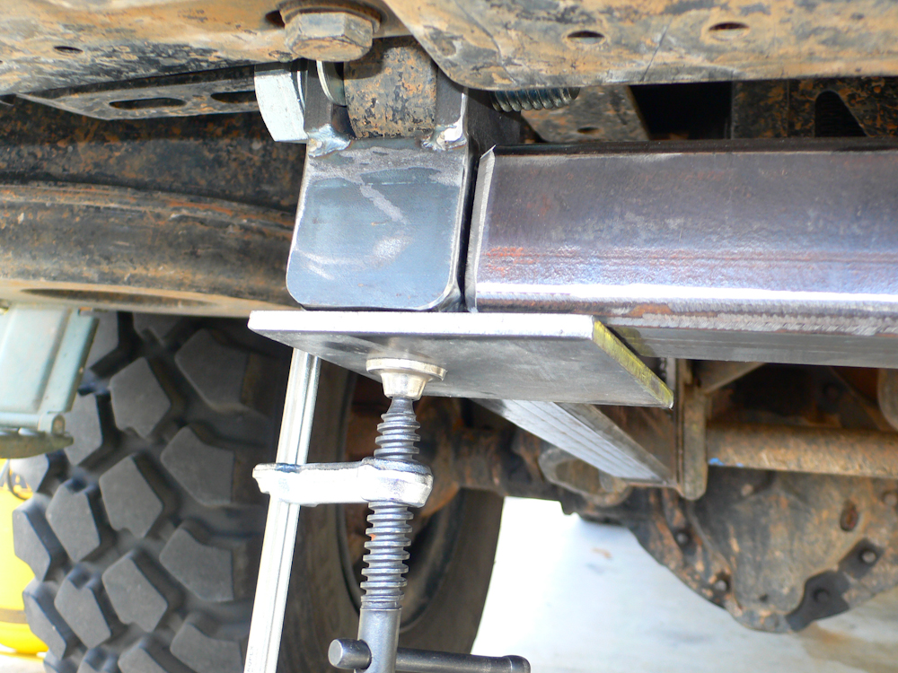
The
fore rail was attached to a short stub of angle that was welded onto
the upper frame rail. Additionally, we had to cut the
handle used for the existing spare tire crane; it was replaced with a
scrap 1/2" drive socket to allow use if needed at some future point.
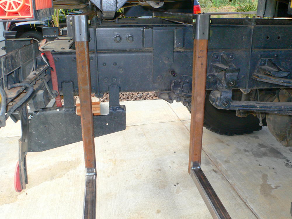
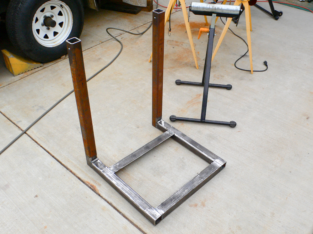
The
descending supports were measured, cut, welded and test installed.
Two
set screws were installed on the lateral and medial sides of the
receiver tube to prevent the assembly from movement.
The
mounting assembly was removed in preparation for painting.
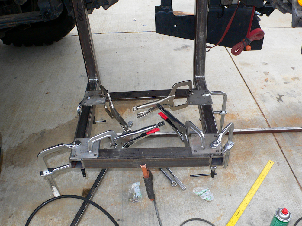
The
second mount was prepared for welding. The clamps were used to
insure that the assembly stayed in the proper geometry during
welding. Sadly, even thick walled material will warp when welded
so care must be exercised.
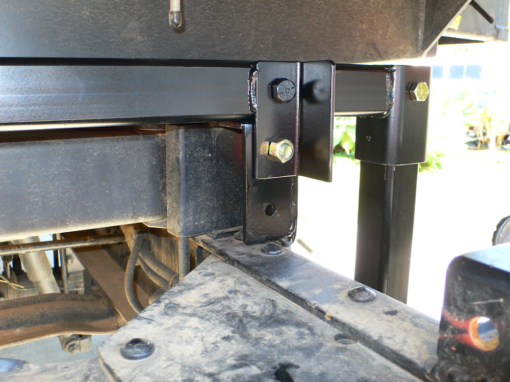
The
aft mounting bar was painted and installed.
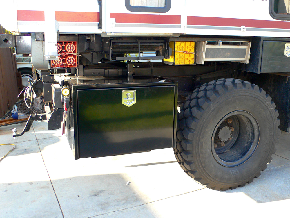
The
fore bar was attached to the frame rails and the cargo box was attached
to the mount with a set of 1/4" pop rivets.
When
the cargo boxes were completed, we took the rig camping in the Borrego
Desert park near San Diego for a few days. The extra storage
space proved invaluable as we were able to transport a substantial
amount of fire wood and the fire ring assembly without impacting
anything else. Score one for the home team. Upon our
return, we attacked the front bash plate issue. During our trip
to Baja, we bent the step bar that allowed access to clean the front
windshield. Inspection of the damage revealed that the bottom of
the radiator was about 1/2" away from being torn out of the
mounts. It was a narrow miss, but it did highlight the need for a
robust protection assembly if we were going to continue doing hard-core
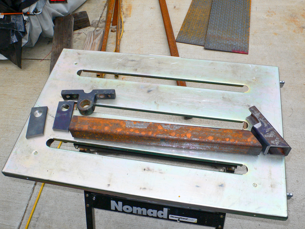
maneuvers while 'wheeling. So, a bash plate assembly was designed
based on the available space and low-impact attachment points on the
frame. The components of the assembly are shown above. On
the left are the descending "ears" that will hook to the tow eye.
The brace bar is 2x2x 0.25" steel tube. The aft mounting block
was machined out of more 2x2 tube. Thanks to Mark Mitchell for
the use of his mill.
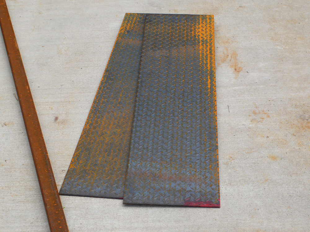
We
went to the steel store and found these 1/4" steel plates that were
nearly the right size.
I
discovered through careful observation and measurement that the 2x2
tube would just fit in the saddle created by the existing mount for the
front sway bar. And, the geometry of the tube was close enough
that we could tap into the existing tow eyes on the front of the frame
without welding. In my heart, I felt that if we welded the bash
plate to the frame there would come a day when we would need to remove
it for some kind of mechanical service action. So, making the
whole assembly removable was a requirement. The proposed setup
did require some machine shop work and fabrication of some odd-geometry
cuts, but other than that, it should be straight-forward.

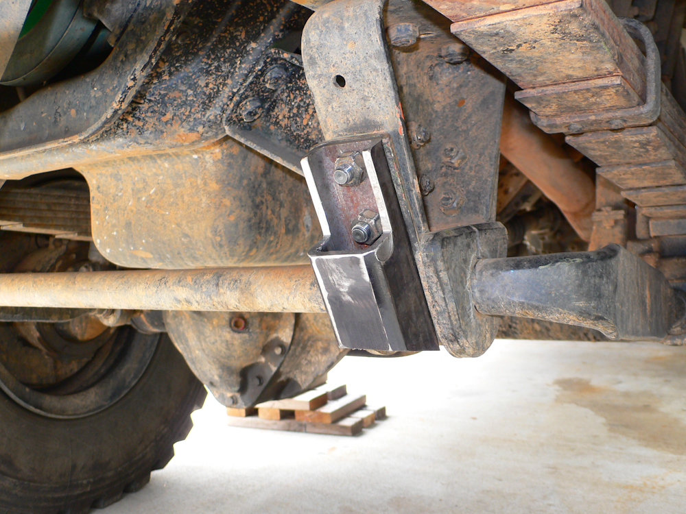
A
test fit of the brace bar as it will sit when connected to the frame.
The
descending ears on the front of the bar will attach to tow eyes on the
frame of the 1017. A 1" bolt was used for the connection.
Massive overkill, but it was what fit the hole in the eye.
Edges
to be welded needed to be chamfered to provide adequate weld
penetration given my wimpy welder. The welder will do a good job,
but only if the edges are prepared.
The
ears and end cap has been installed on the brace bar. Now we get
the cross member lined up for welding.
The
finished product ready to have the 1/4" diamond plate attached and then
be painted. We cut the 1/4 " plate with a new saw blade purchased
specifically for this task. The blade is called a "Diablo"
(available at Home Depot) and it fits in a standard circular saw.
The blade is carbide tipped and cut through the 1/4 plate like it was
butter. And, there were no burrs on the edge of the plate!
Kathleen and I were totally impressed.
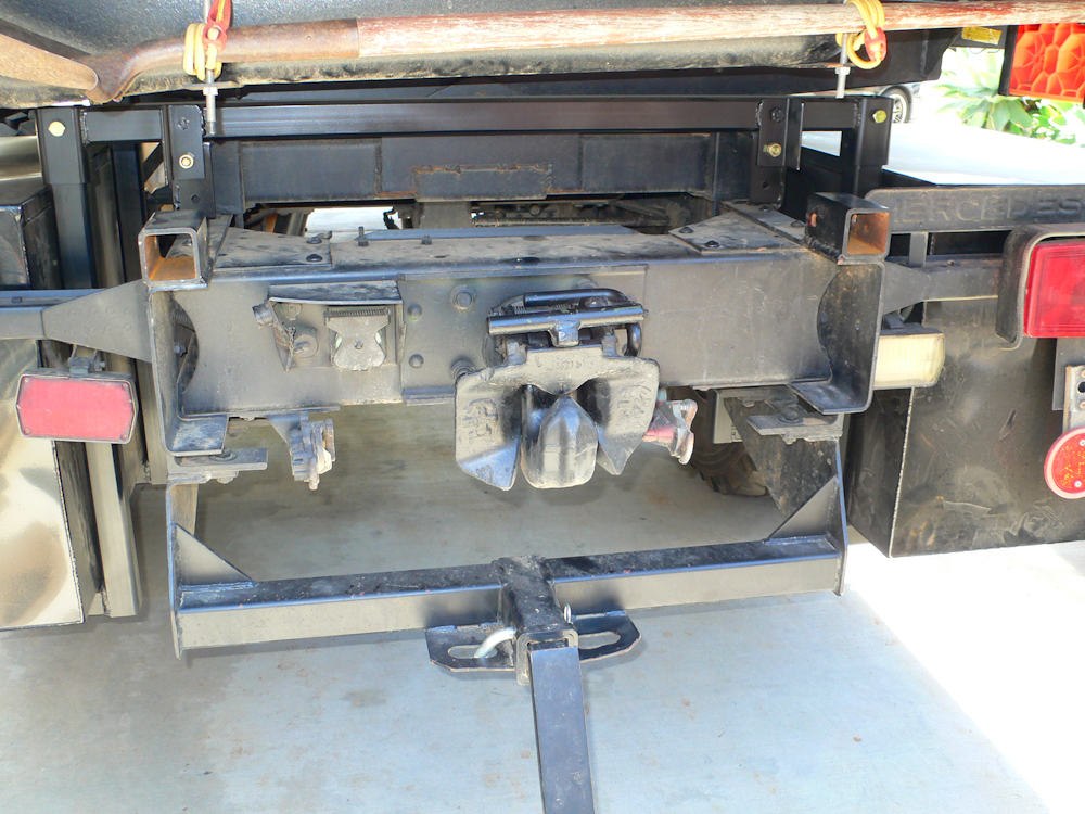
Once
the bash place was painted and installed, we turned our attention to
the rear of the truck. Our expensive Yeti cooler is too big to
fit in even the biggest cargo box, so an alternative solution will be
needed. Our plan calls for construction of a frame that plugs into the
previously-installed hitch receivers that were welded to the top of the
frame rails. An additional receiver will be placed on top of the
conventional hitch receiver to provide additional support and allow the
use of the trailer hitch for towing without the requirement to remove
the frame.
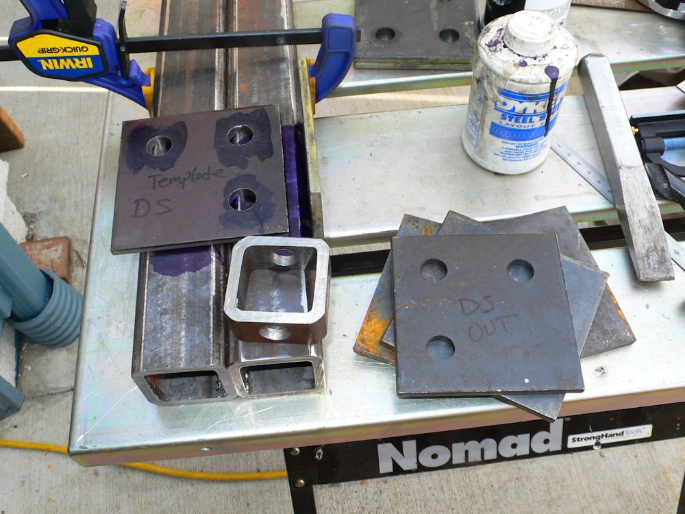
The
deck on the platform will fold up when not in use. Above, the
hinge components are fabricated and checked. This design will
have some pretty tight tolerances to prevent rattles, so and part of
the construction we purchased a (better) used drill press to allow
drilling 5/8" holes through thick walled material.
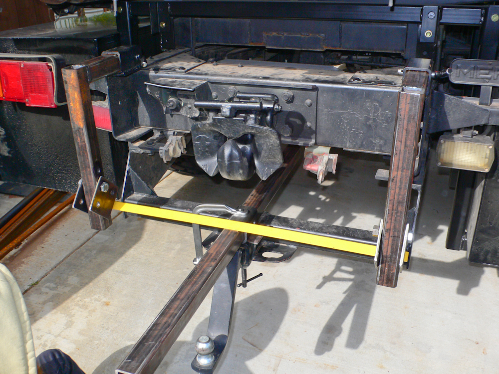
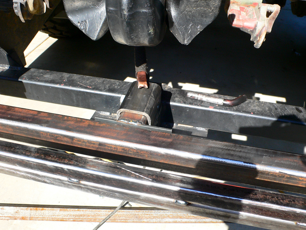
The
descenders were carefully welded to prevent warping and then test
installed to determine the measurements of the balance of the
mount. Above, the secondary receiver mount was test positioned on
the trailer hitch frame to determine the fit before cutting.

The
descenders were held in place with conventional hitch pins. Note
that a 1/4" shim plate was needed under the auxiliary receiver to get
the geometry correct.
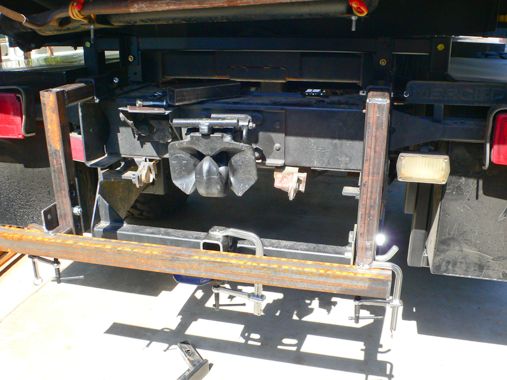
The
geometry and rotation of the hinges was tested by clamping some spare
angle to the hinge components.
The
lower receiver components were cut, drilled and welded. The deck
components were fabricated from stacked 1x1 tubing, visible at the
bottom of the photo.
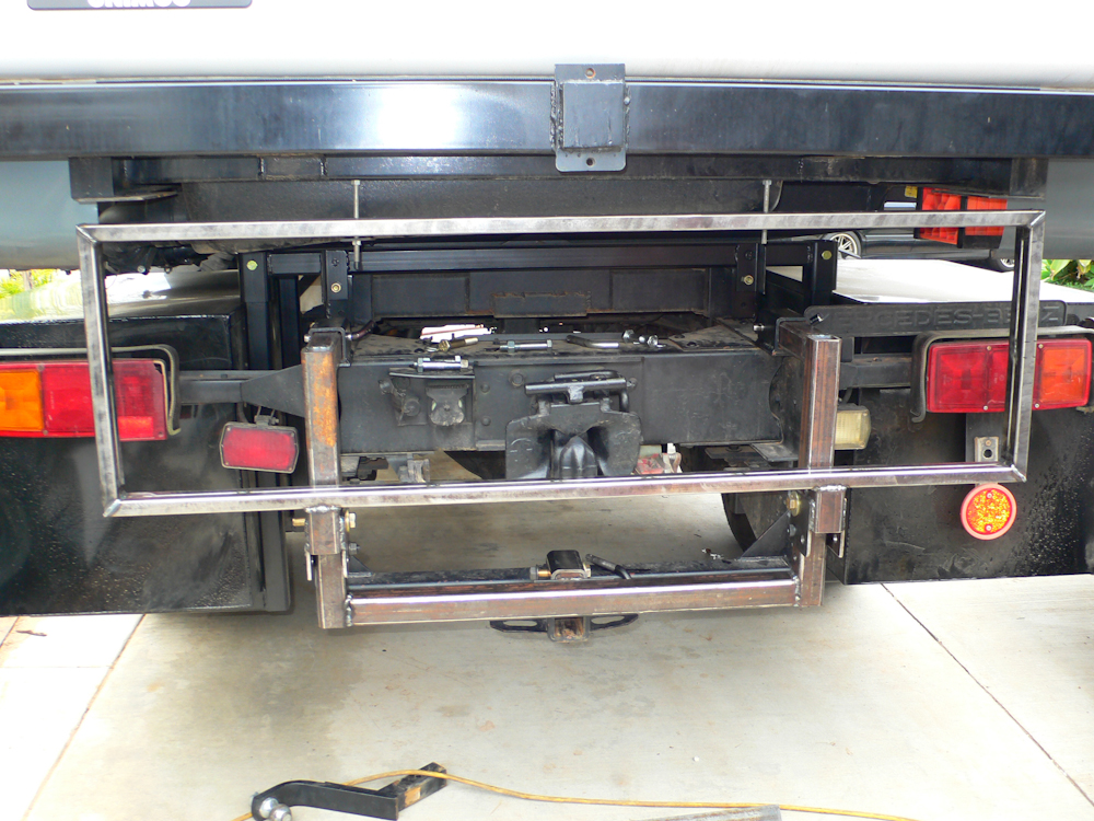
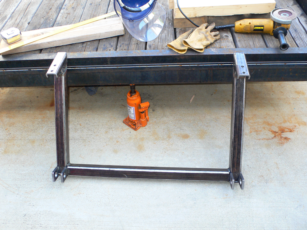
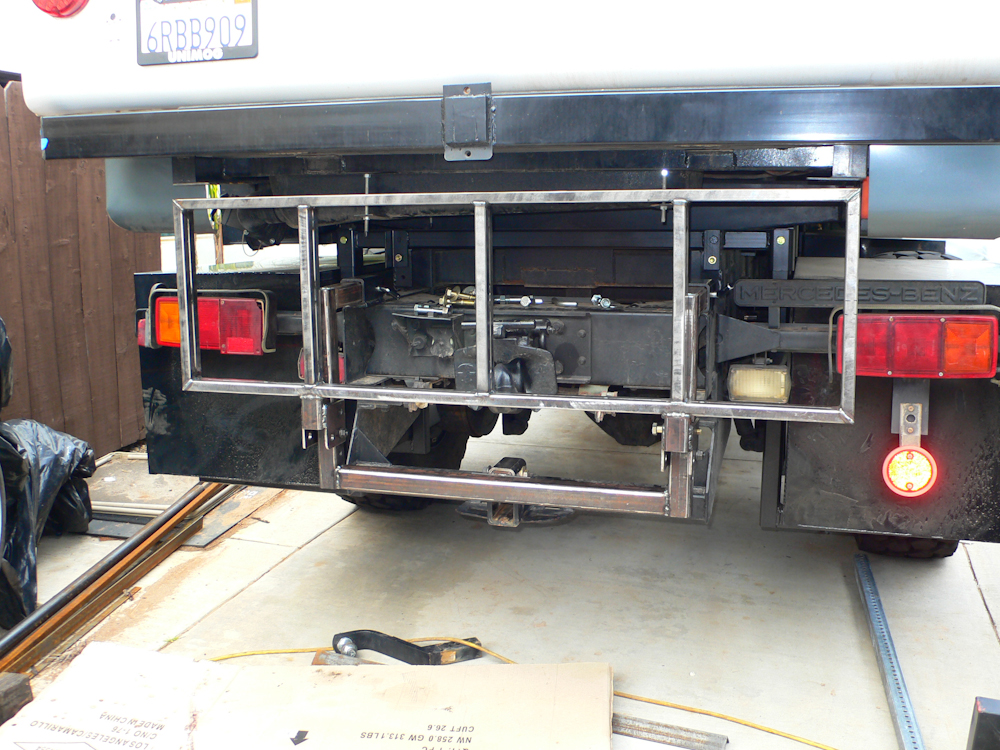
The
deck frame was completed and then re-installed to the truck for
further hinge testing. The photo above shows the deck in the
retracted position.
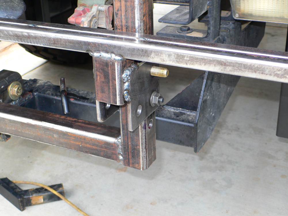
The
photo above shows the hinge details. The welds in the photo above
look funky; the reason is that to prevent warping, we could only weld
about 1/2" at a time before letting the work piece cool down.
Kathleen assisted by using the air gun to accelerate the cooling.
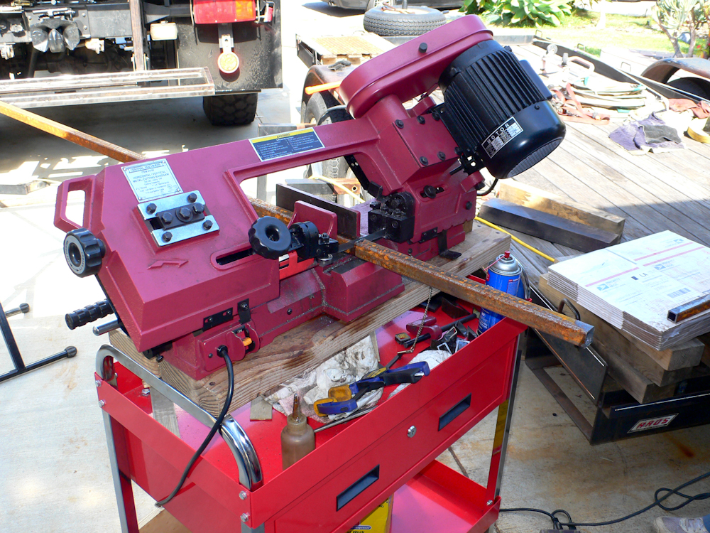
My
Harbor Freight band saw served us quite well during this project.
While not quite the quality I would have preferred, it cost about 1/5
of what I wanted and the work product was adequate to meet our
objectives. To be sure, there was a substantial amount of setup
to get the angles correct for the cuts, but that would have been the
case with any saw. After weeks of leaving the saw in the driveway
under a tarp (it is very heavy), I finally went back to Harbor and
purchased a cart to put it on so I can easily roll it into the garage
at the end of the day. Above, Kathleen cuts the internal deck
support members.
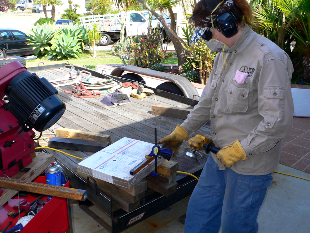
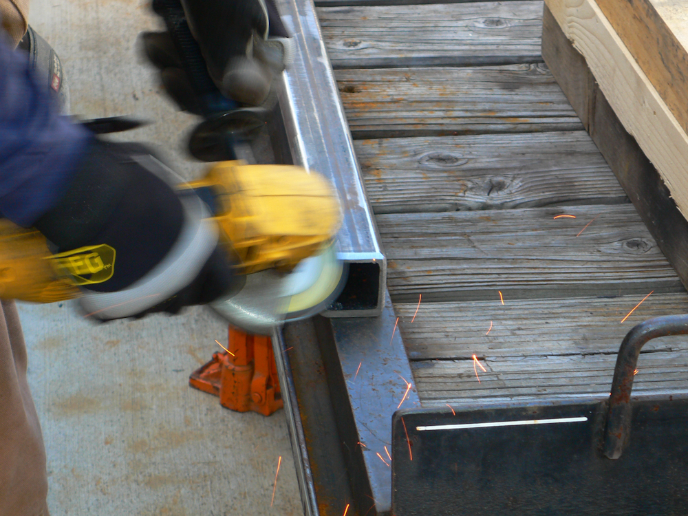
My
garage is not big enough to handle 20' lengths of steel tube, so we
left it sitting in the driveway for the duration of this project.
Rain rusted the hell out of the material making a thorough cleaning
necessary before final assembly and painting. Above, Kathleen
hits the tube with the angle grinder/wire wheel combo to remove the
rust.
The
additional support members were positioned and welded into the
deck. Again, in the photo above, the deck is shown in the
retracted position.

Finally,
the #9 expanded metal cover was added to the deck creating the load
bearing surface. The assembly is quite rigid and should easily be
capable of handling 500 pounds of cargo and still be retractable when
not needed. It should be noted that the height of the deck does
not impact the departure angle of the truck. The cargo boxes
determine that angle, followed closely by the bottom of the trailer
hitch assembly.
| Previous Adventure | ||
| Trip Home Page |
Photos and Text
Copyright Bill Caid 2011, all rights reserved.
For your enjoyment only, not for commercial use.