We continued our enhancements to
the 1017A. Generally speaking, we were limited by the ability of
our parts vendors to deliver our needed components to us in a timely
fashion. Once we had all the necessary stuff, things went pretty
smoothly. This section of enhancements was focused on installing
body-mounted tool boxes and the super-single tires/wheels. We
ordered 8 tool boxes with the intention of installing 5 on the camper
body and 3 "big" boxes on mounts attached to the frame itself.
Mounting the camper boxes was a challenge due to the odd geometry of
the camper. We did not install the bigger boxes during this
segment due to the arrival of the wheels and tires. The wheels
were ordered through our parts supplier and were delivered through
Mercedes in Germany. The whole cycle took almost 4 months end to
end. The tires were purchased online and arrived after only a
week or so.
The photos below are what we saw.
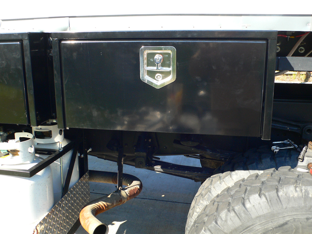
For the cab, we ordered
3-24"x14"x16" boxes and 2-30" boxes. One 24" box was used for the
utility connections and the 30" box will be used for general
storage. Brackets were fabricated and welded to the camper
frame. The boxes were mounted flush with the underside of the
floor of the camper between the frame rails.
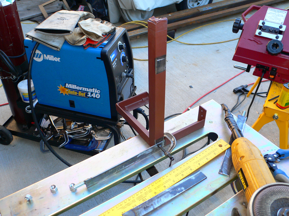
The rear mounting frame was much
more complex and had to be fitted, fabricated and primed before welding
to the frame. Above, the final fabrication actions are performed
prior to welding the frame into place.
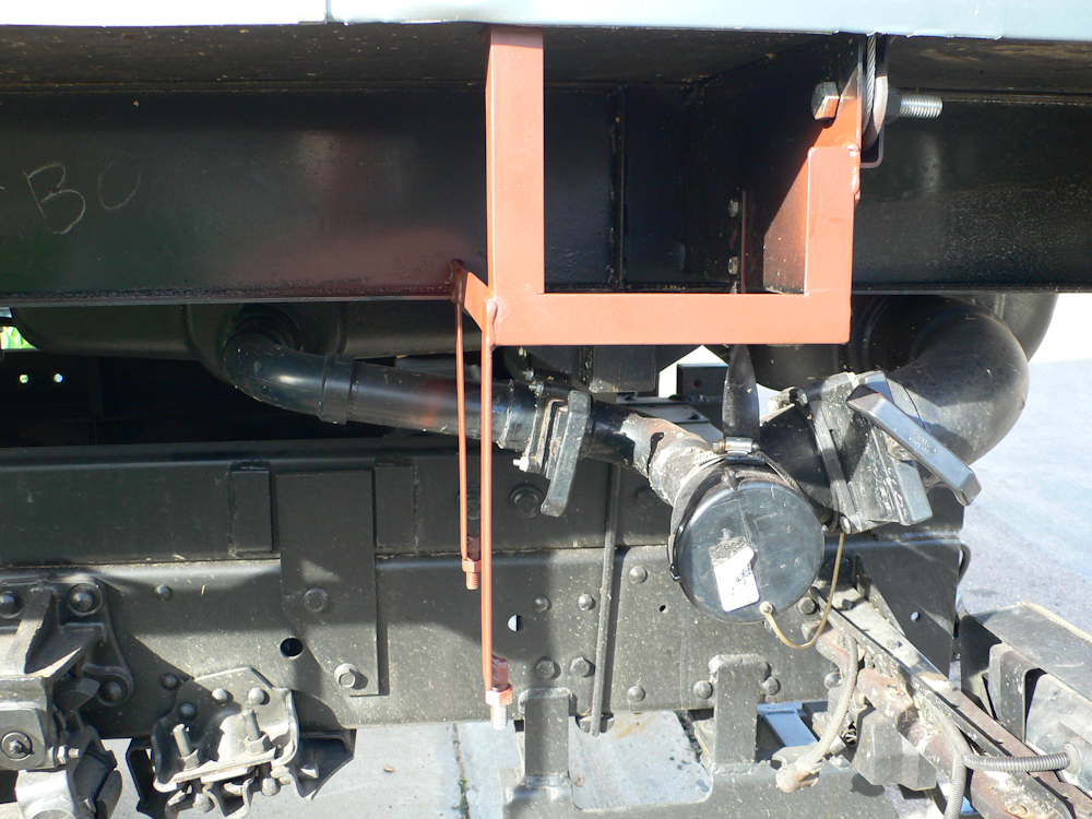
The frame was welded into place
and the welds were then primed prior to painting.
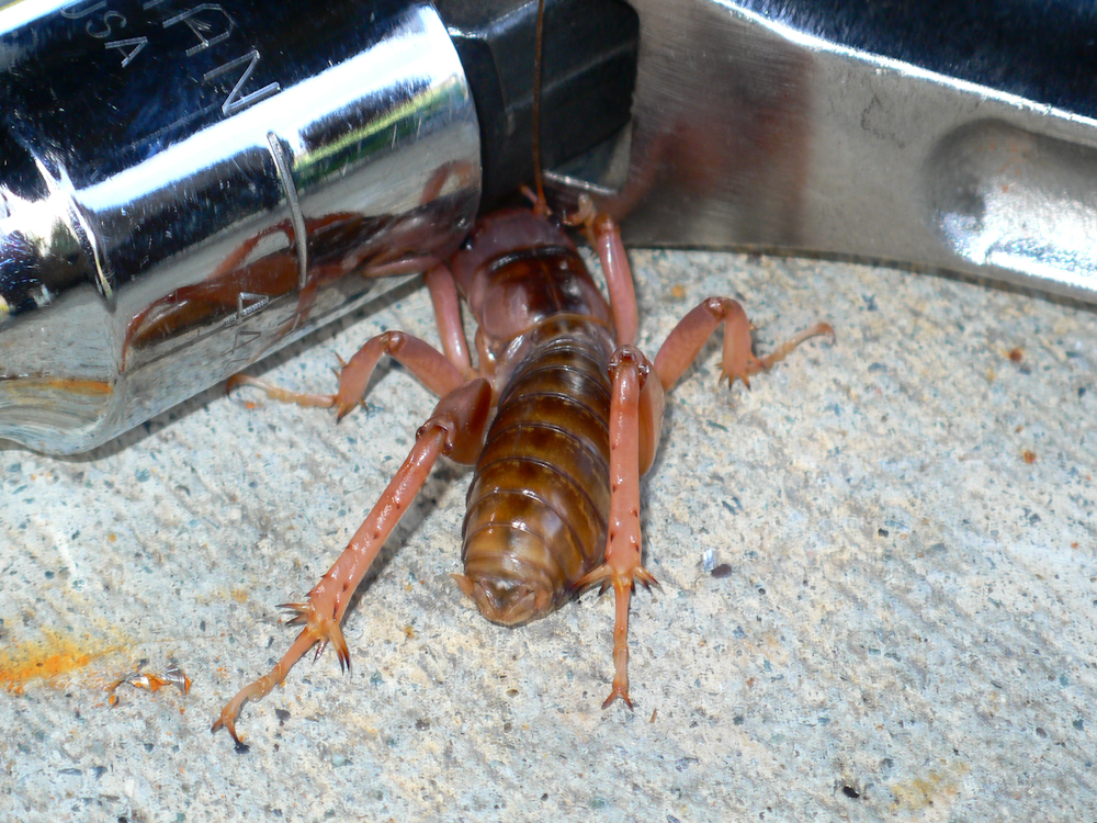
Whoa!! WTF is this??
This gnarly insect is about 1.5" inches long and I discovered it
between my knees as I was working under the truck.
After the 3 tool boxes were
installed, we moved on to tires. I traded Roberto Espinoza for 4
Michelin 395/85R20 XZL tires that he had. His office was flooded
during the recent rains, so I was storing them for him. After the
balance of my tire/wheel parts arrived, I traded him the 4 I had for 4
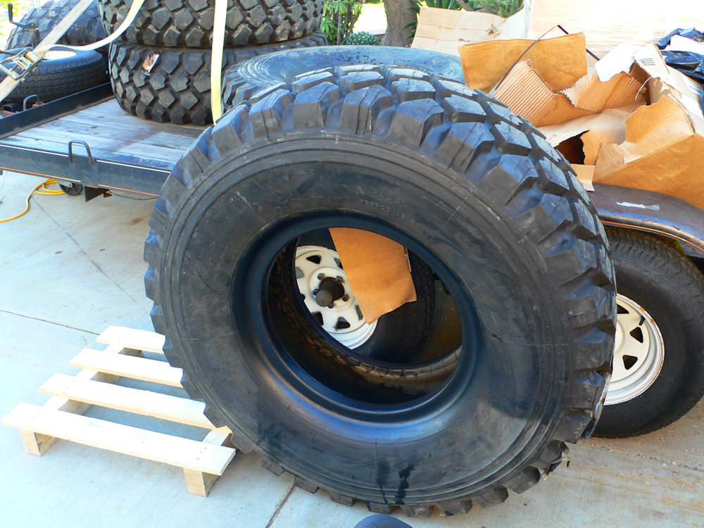
more that were ordered online. These tires are brutes; big and
heavy. Notice the diameter of the tire relative to my car carrier
trailer.
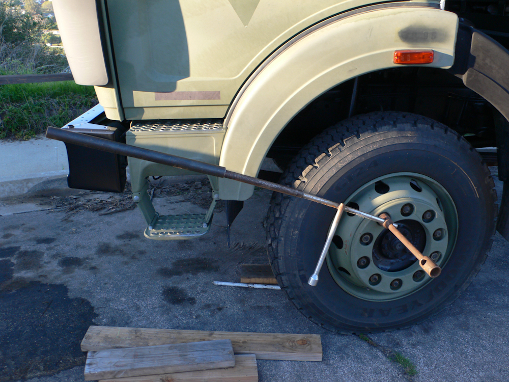
The first thing that had to happen
was a "test fit" to insure that the over-sized tires would fit as
needed. To do that required removal of the existing 22.5"
heavy-duty truck tires. These lug nuts were TIGHT and required
several cascaded cheater bars to provide sufficient torque to crack
them loose. The bar that came with the truck did not fare well,
so we resorted to using an X wrench that came with my 1300.
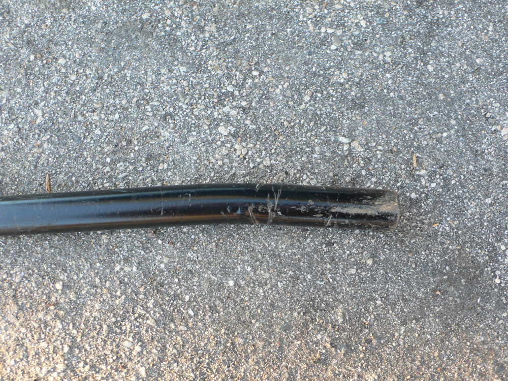
The bar that came with the 1017A
was not up to the task; it was just not robust enough to handle the
torque. It bent like a pretzel under stress. The photo
above shows the bar AFTER it was straightened. I have
subsequently purchased several hardened bars to use with the cheater.
The test fitting went OK, there
were no "unknown" interferences. In the photo above, the tire is
not fully mounted. There is no locking ring on the tire and no
valve stem in the rim. See below for details.
The special valve stems needed for
installing the tires were ordered but not here, so we moved on to
electrical actions. High-current cables were strung from
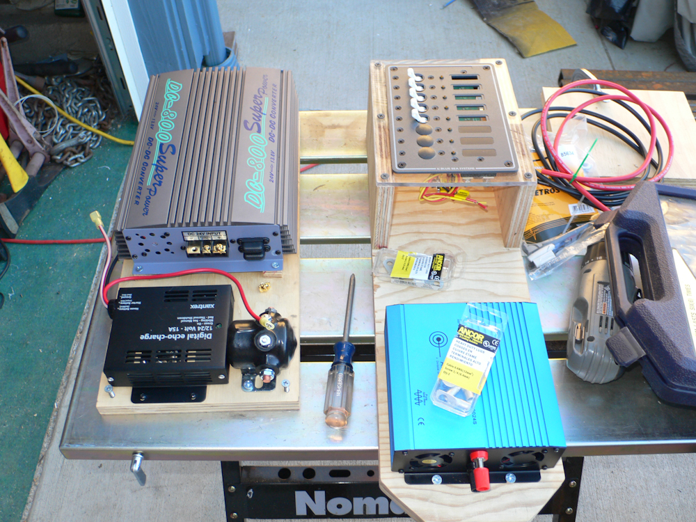
the 24V battery array to the cab of the 1017. Mounting posts for
the electrical connections were attached to the fender and preparations
were made for the final run of cable into the cab. The mounting
boards for the electrical components were cut and the components were
mounted. Above are 2 boards that will be attached into the "cargo
bubble" on the back of the cab. The bubble has a vertical
stiffener and on the driver's side the left board will be
attached. The other board will be on the passenger's side.
The left board has the 24V->12V converter, echo charger and 24V
enable solenoid. The right board is the 12VDC circuit breaker
panel and 24V->120VAC inverter for cab appliances like laptop and
cell phone chargers. I did not complete the electrical
installation as the remaining tire components finally arrived and we
switched back to that task.

The front of the truck was jacked
up and the OEM wheel was removed. The 1017A has drum brakes
all-around and these are big drums.
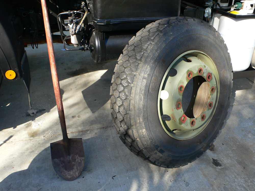
Why is that shovel in all these
photos? The answer is that it is the trick to changing large
tires. A standard #2 spade-point shovel provides an excellent
lifting method for large tires. It takes a hard task and makes it
easy. In fact, you can change a tire with only one person if you
have a shovel and the truck is not jacked too high. In addition
to lifting, in also acts as a "sled" to slide the tire away from the
wheel when removing the tire from the hub. Frankly, I doubt that
it would be possible to do this action without this sort of tool.
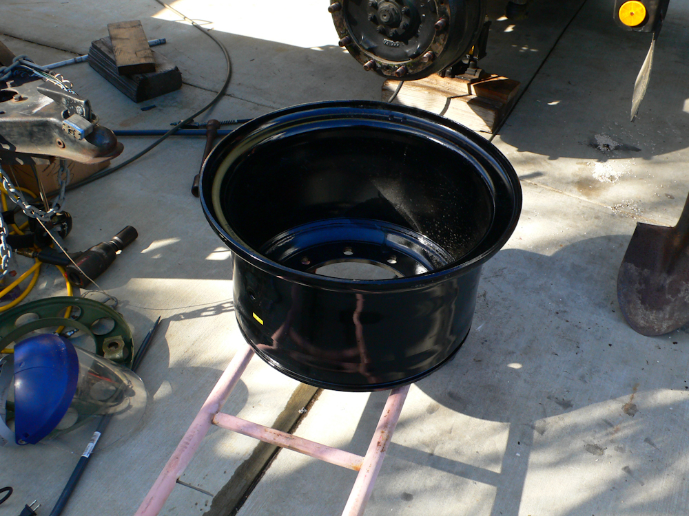
The new super-single wheels are
made of 12mm thick rolled plate. These wheels are very, very
heavy. These are 4 part wheels: the cup, the sealing
gasket, the outer flange, and the locking ring.
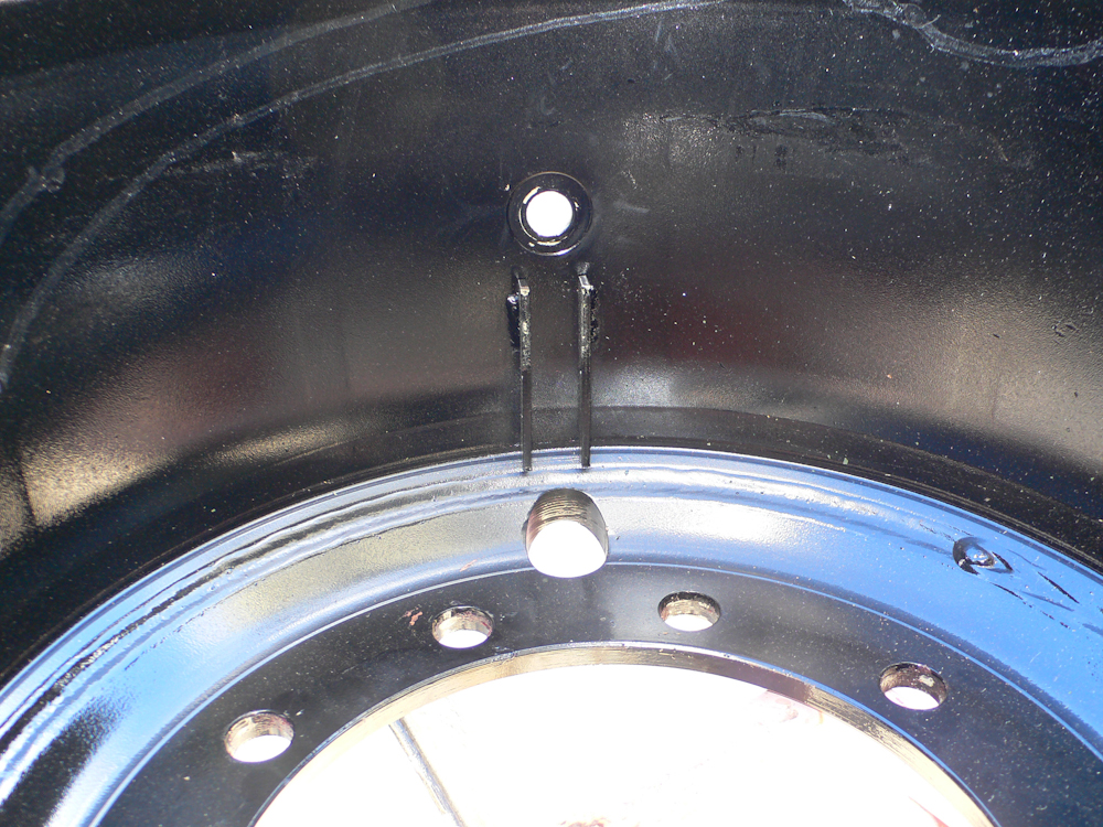
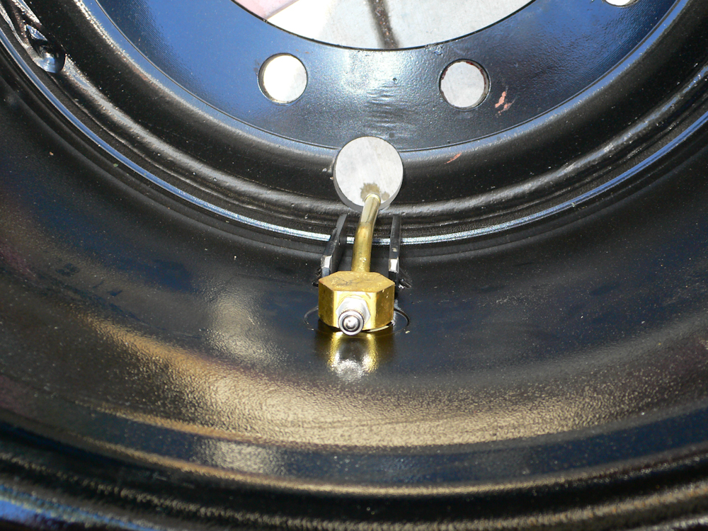
The inside of the wheel has
protection plates for the valve stems. The corner of these plates
would be ground down to provide clearance with the brake drums.
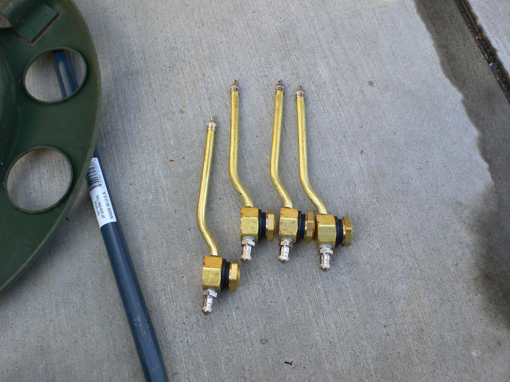
These valve stems were destined
for a US military 6x6, but also fit these rims. These were about
$35 each, but a far cry from the $100 each that Mercedes wanted for
something that could only be filled from one side of the wheel.
The bar on the left of the photo above is my new Ken-Tool hardened bead
breaker/cheater bar for cracking lug nuts. I got it online from
Gempler's. They have tons of industrial tire tools and fast
delivery.
The mounted tire valve stem before
the corners were ground off.
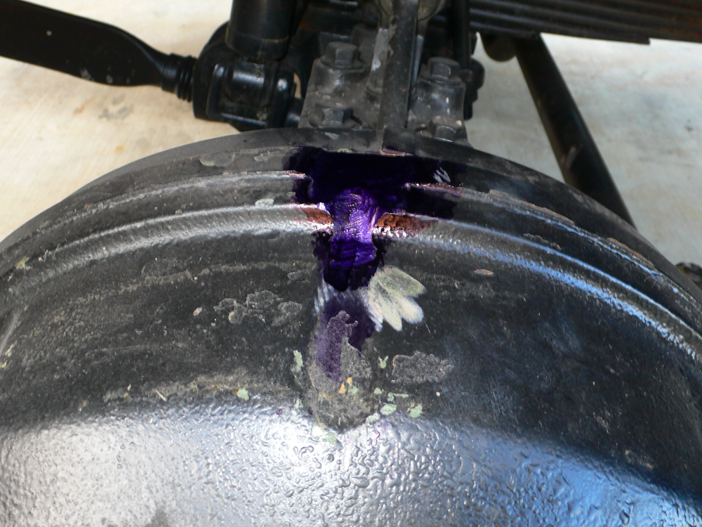
To make the stems fit, a trough in
the drum was cut with a pneumatic die grinder and carbide bit. I
used layout dye to test for mechanical interferences with the
stem. A number of grinding passes were required before the trough
was deep enough.
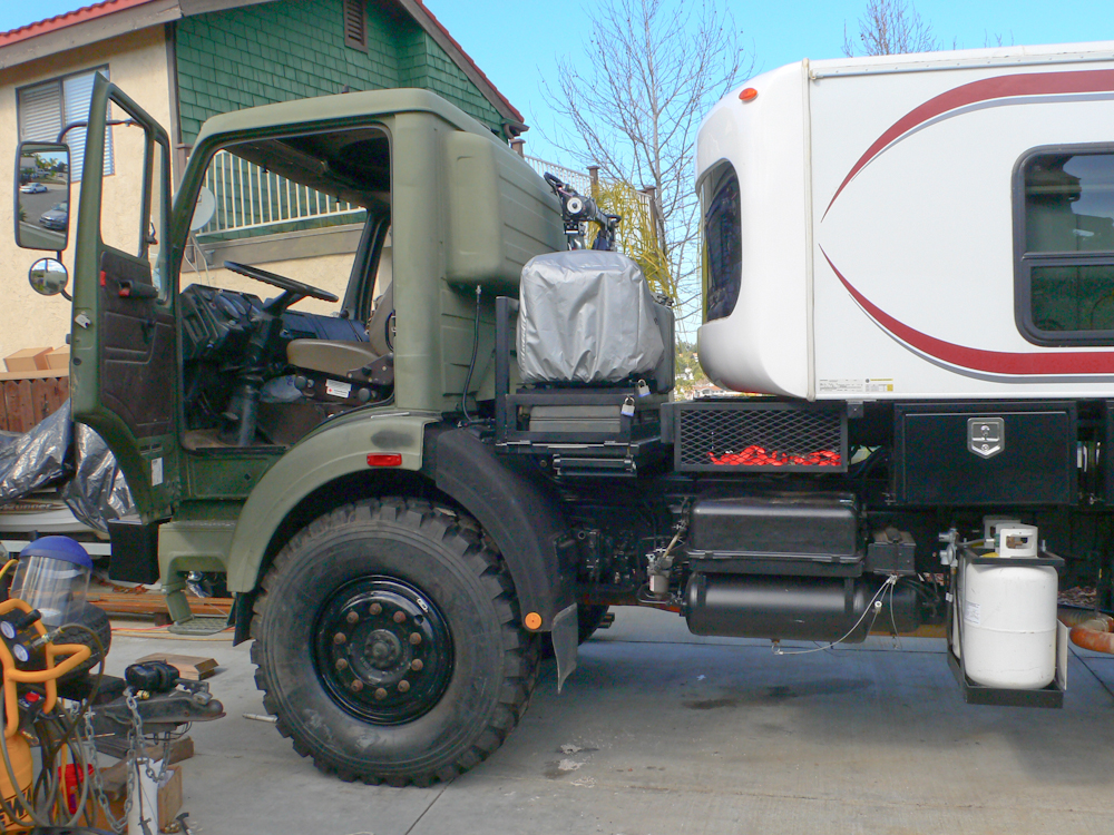
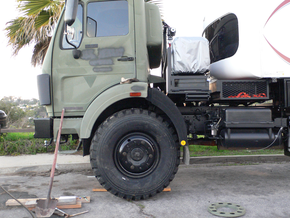
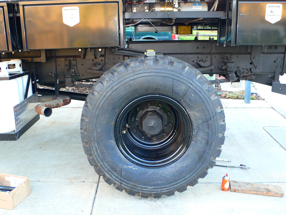
The front tire was installed after
the hub fit in the trough. These big tires totally fill the wheel
well. In fact, portions of the fender will have to be cut to
eliminate possible intereferences when the truck is off-camber.
Note the electrical cable coming out of the underside of the cab cargo
bubble. This is the 12 echo charger cable to change the house
batteries when the truck is running. The cab is 24V, so a voltage
conversion is required as well as a charge controller circuit (echo
charger) to accomplish the mission.
In the rear, the truck was
equipped with dual wheels when shipped from the factory. 2 rear
wheels were replaced with one super-single. Note that the "cup"
is in on the rear, out on the front. In the cavity above the
wheel is the house lift hydraulic pump.
The first tire that we installed
developed a leak due to operator error, so we pulled it off the rim and
addressed the situation. Afterwards, we pulled the truck into the
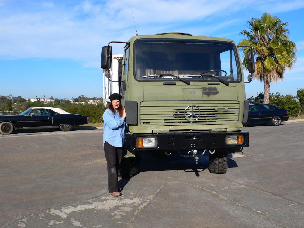
street as a test. Note that the truck is now quite high relative
to Kathleen's 5'8" height.
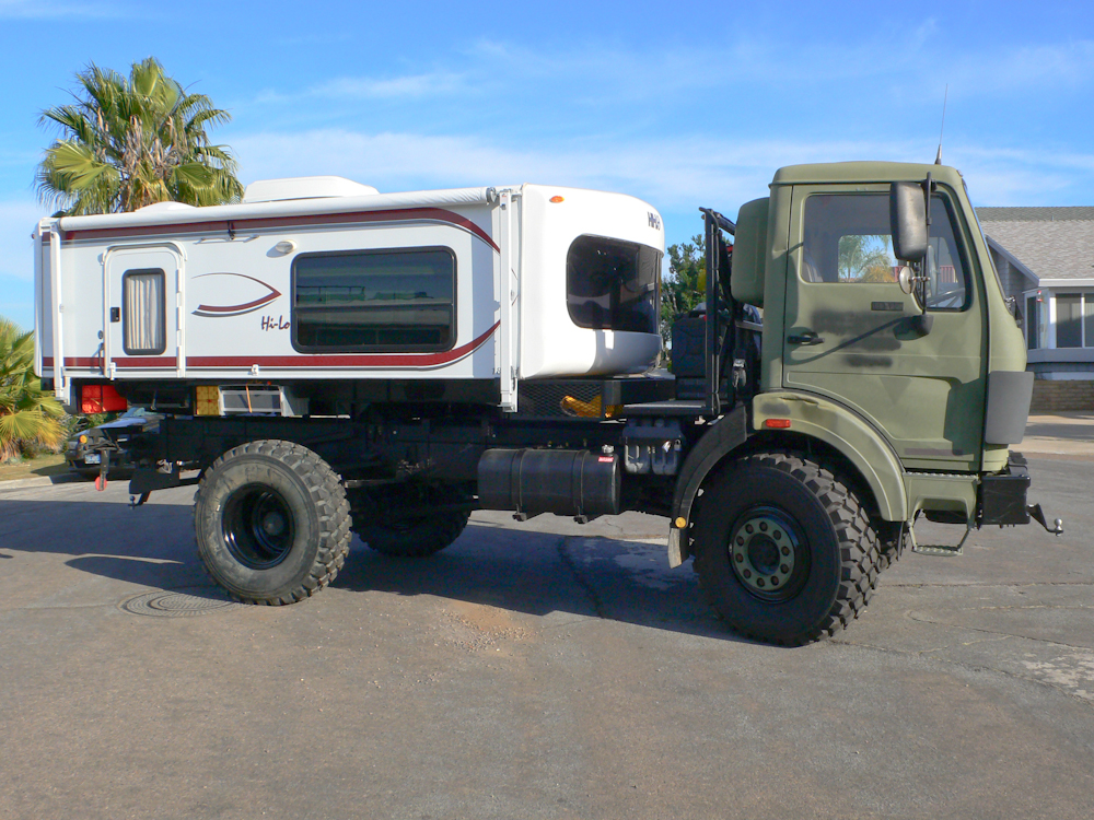
None of the tool boxes on the
passenger's side have been mounted yet. But at the rear, under the
camper, you can see the mounting frames for the leveling blocks and the
storage area for the stairs.
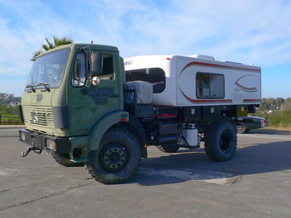
The 3 tool boxes on the driver's side are clearly visible above.
Next up: body work to cut a portion of the front
fenders to remove the possibility of mechanical interferences with the
tire. We will also remove the leading mud flaps on the front of
the tire. The cab electrical must be completed as well as the
mounting the remaining 5 tool boxes.
| Previous Adventure | ||
| Trip Home Page |
Photos and Text
Copyright Bill Caid 2011, all rights reserved.
For your enjoyment only, not for commercial use.