We had several down days
while Rob was attending to family matters with his new twins.
When we started work again, the objective was to attach the frame
members to the frame and perform a frame articulation test.
The photos below are what we saw.
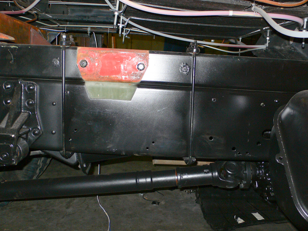
The original red factory
primer can be seen where the original bed mounting bracket had been
before it was relocated rearward about 2 feet. The resulting
space will be used for mounting a frame to hold 2 30# propane
bottles. Unlike the Alaskan camper, this camper has a much bigger
appetite for propane due to the refrigerator, water heater, forced air
space heater and cook top/oven. And, I may add a catalytic heater
as well.
The camper had sat on the
truck over the weekend and we had plenty of time to measure things
required for attachment of the pivot points. In the end, due to
flexure in the camper body itself, we elected to increase the offset
from the frame by 1/4" and add 3/8" support shims to the hard
mount. The reason was that frame flex was causing the side door
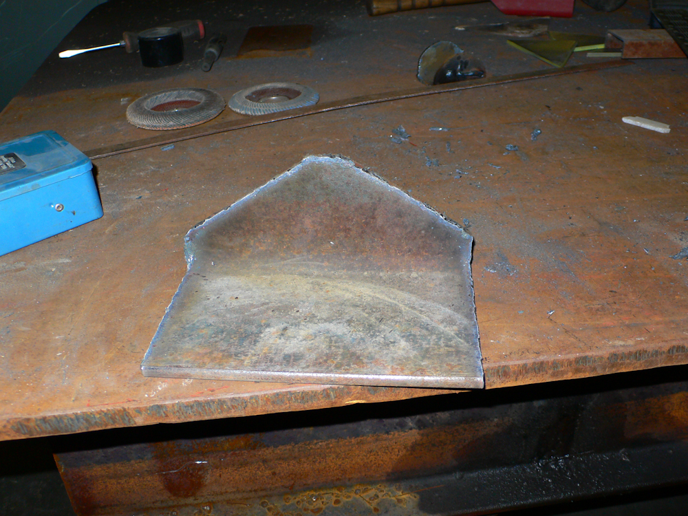
to be out of plumb. The mounting bracket above was being cut out
of 3/8" 6 " angle iron.
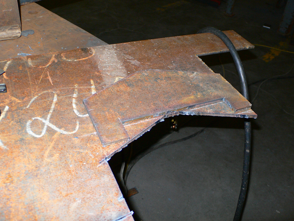
The other half of the mounting "ear" was made out of 1/4" plate.
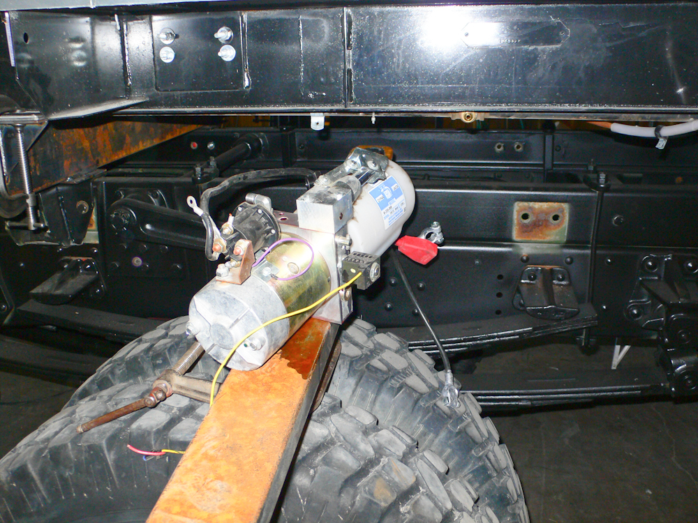
The hydraulic lift pump
used to raise the top was removed from the tongue area and set aside
during the welding to provide needed access. In the end, the pump
assembly will be relocated over the driver's side rear wheel very close
to where it is currently sitting.
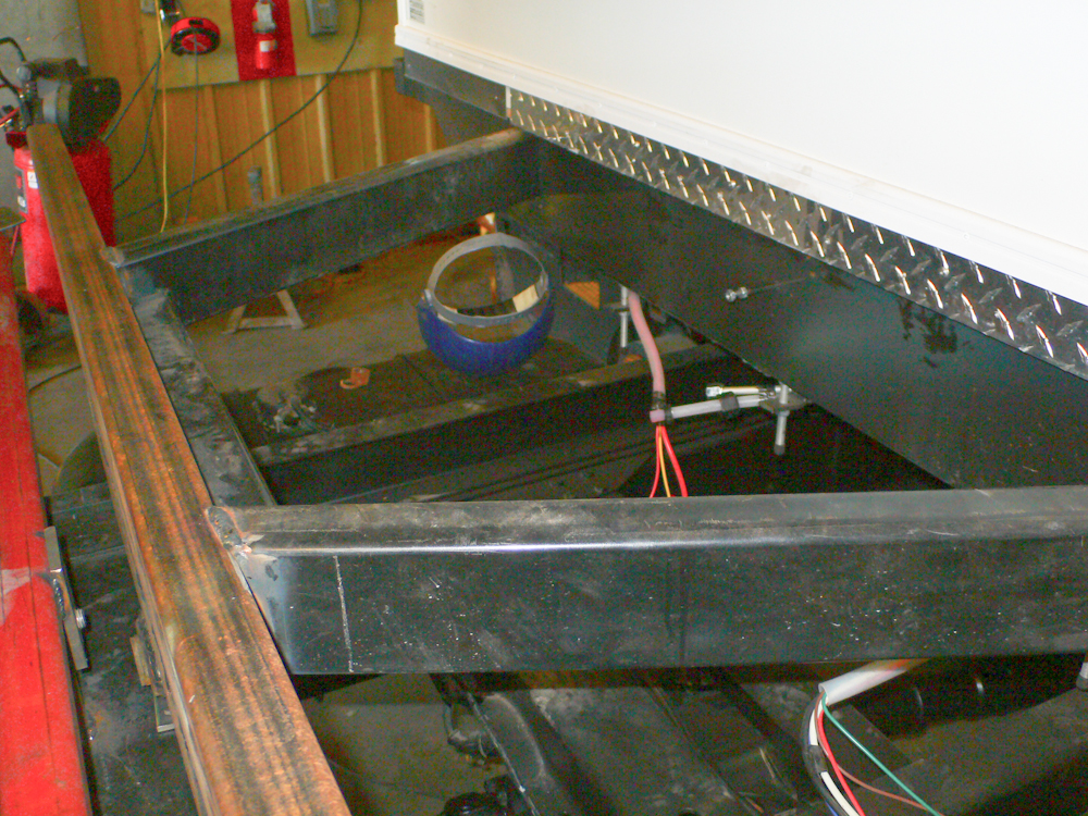
The hydraulic lift pump
was moved from the tongue area to provide room for the 250# of lead
acid batteries that will power the camper. The battery tray will
be in the open area between the frame rails in the photo above.

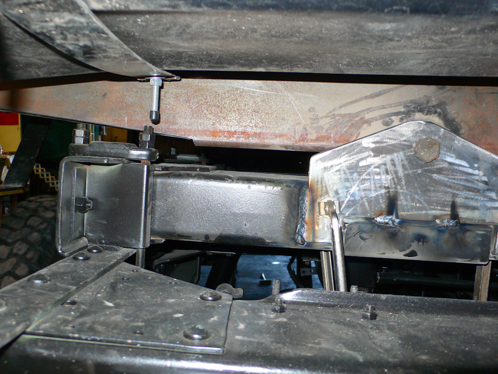
The front vertical pivot
ear was welded onto an existing frame member.

The thicker angle bracket
was also welded to the same member next to the support for the spare
tire rack.
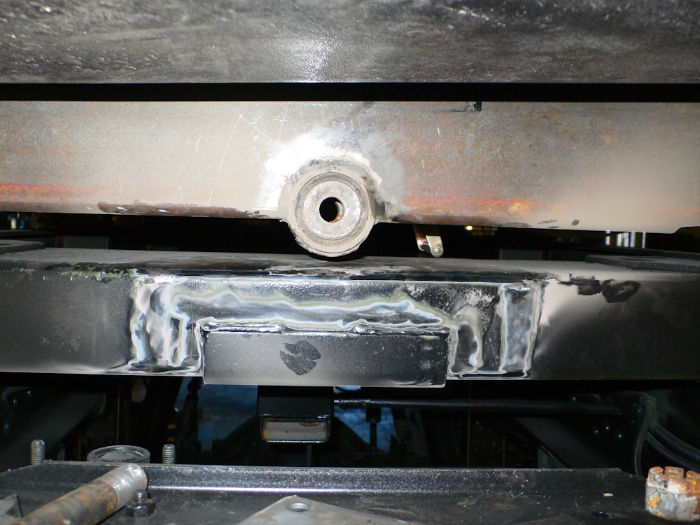
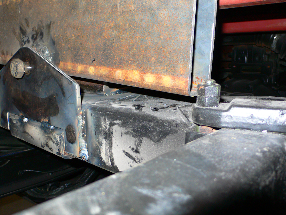
When the pivot bolt was
installed in front pivot and the supports for the rear pivot were
removed, there was about 7/16" of "float" on the rear frame
member. Our objective was 1/2", so this was very, very
close. We shimmed the rear to the desired 1/2" and then welded
the vertical ear onto the rear cross member. In the photo
above, you can see where the paint has been removed in anticipation of
welding.
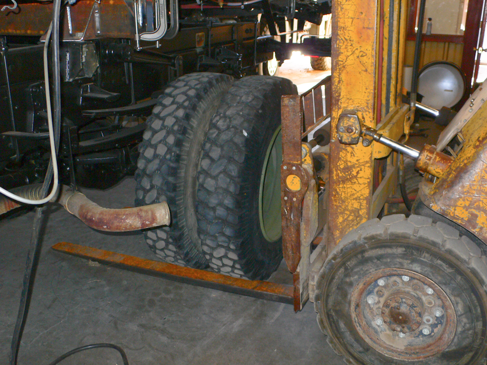
The front and rear pivots
were welded to the frame cross members. The center "hard mount"
was not yet welded, but rather just clamped to the main I beams of the
trailer. We were confident in the mounting, so we decided to
perform an articulation test to insure that our mounting strategy was
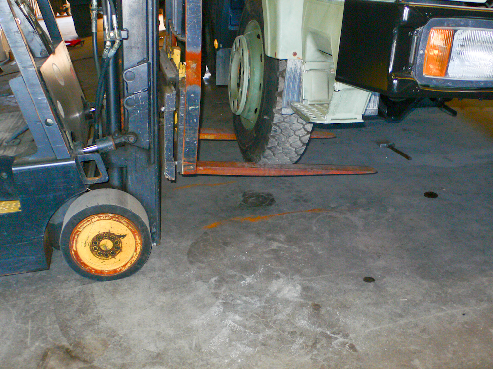
correct and that there would be adequate clearance. The plan was
to use the fork lifts to elevate opposite corners of the truck and see
what happens with respect to articulation of the frame rails of the
truck relative to the camper frame. Above, the forks of the fork
lift were positioned around the tire prior to the lifting.
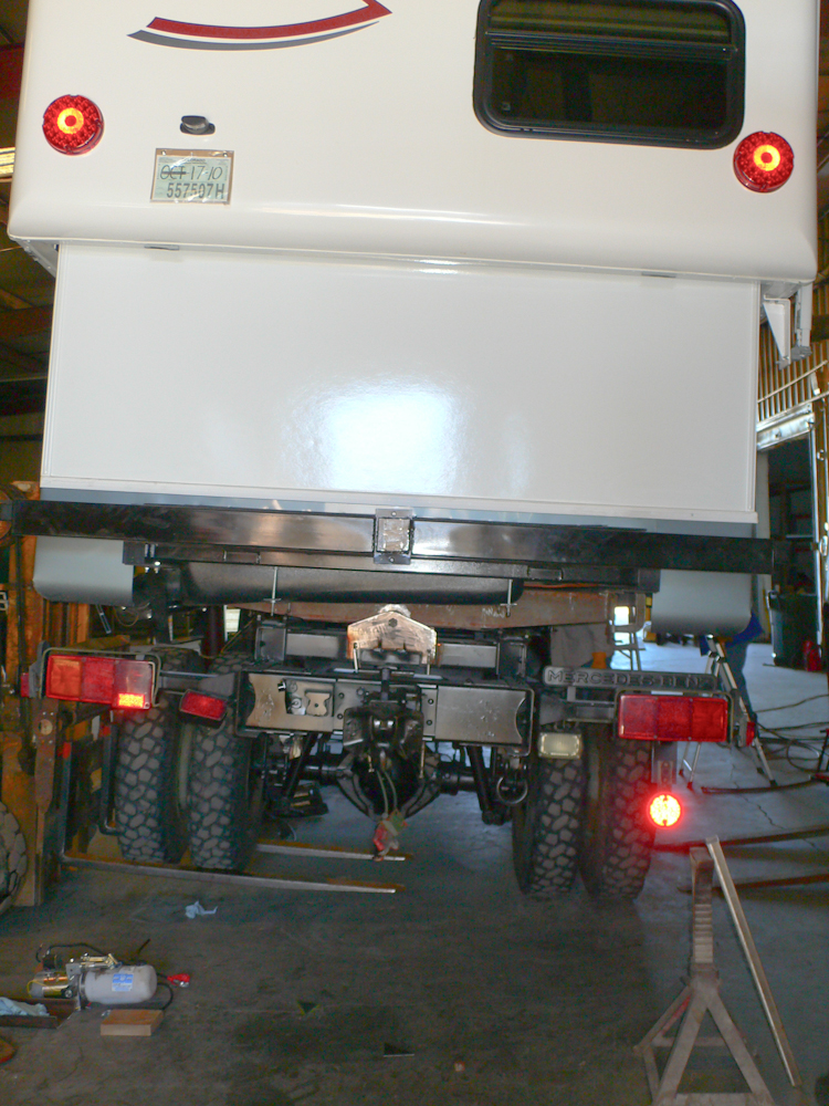
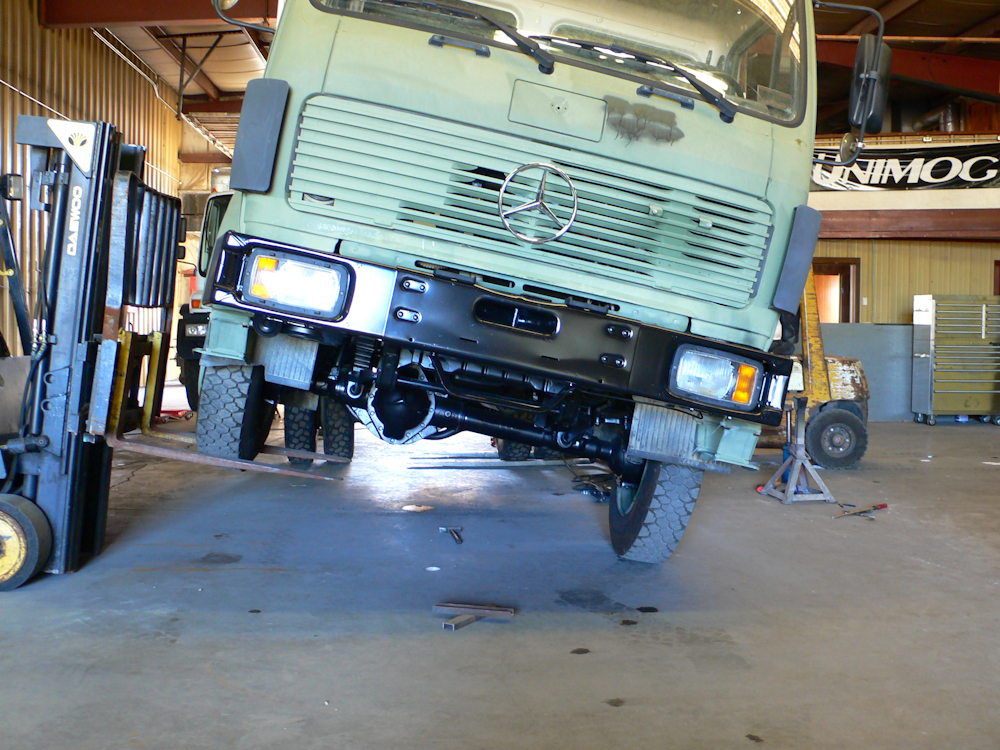
As the rear tire is
lifted, you can see the truck frame rails twist. The camper
mounting frame is staying relatively level, at least so far. This
lift was only about 7".
As the lift height
increased, you can see the camper start to tilt. Note that the
roof of the camper is elevated and would never be elevated for travel
unless there were an emergency or a mechanical failure.
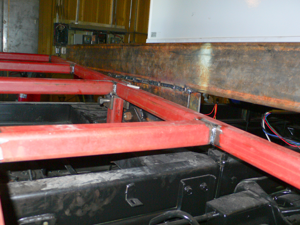
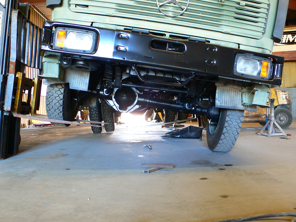
As the opposing front
wheel was lifted, you start to see substantial articulation in the
frame. Above, note that the red frame (tire mount) is also a
3-point design but is hard mounted close to the rear end of the
cab. The brown, rust colored beam is part of the camper frame and
is also a 3-point mount, but with a longer distance between the hard
mount and the pivot point.
The front wheel is about
20" off the ground at this point.
The end of the frame rail
is getting pretty close to the cross member. I did a set of
calculations to determine when the contact would occur and the
theoretical vs. empirical difference was quite small.

As the lift height
increased the flexure angles increased as well.
The photo above is about
22" of lift on the front and about 10" on the back. The rear fork
lift had hydraulic seal issues which prevented the height from being
constant due to seepage.
It looks scary, but it is
only about 12 degrees of slope.
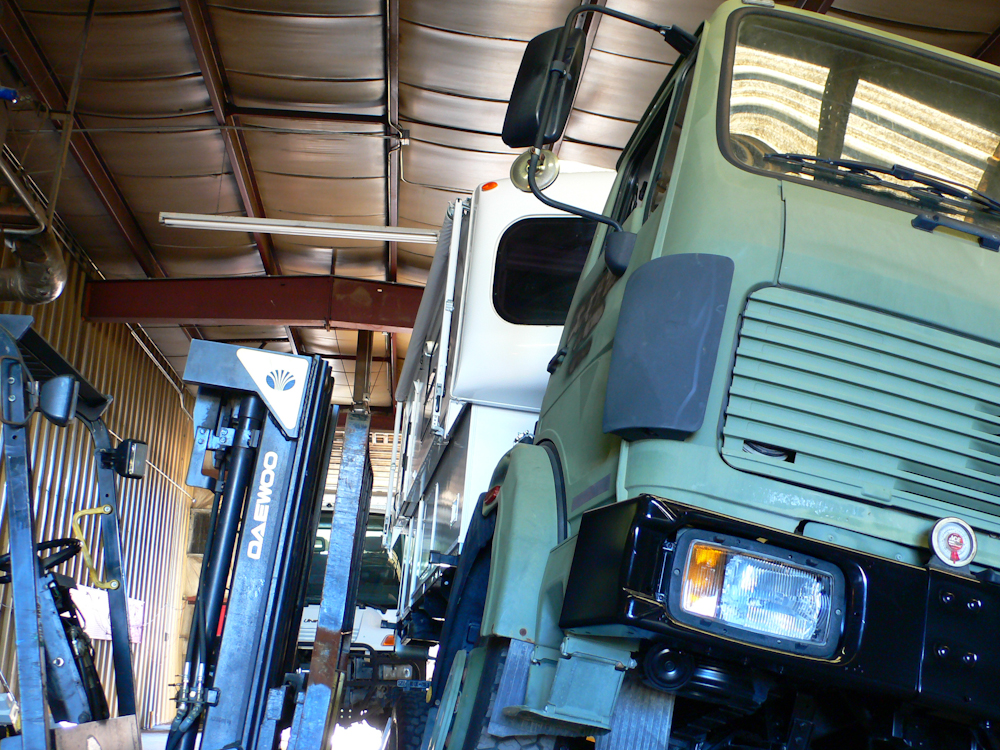
The camper frame was
measured at 5 degrees of slope, nearly constant from front to back of
the frame while the truck slope was about 12 degrees.
| Previous Adventure | ||
| Trip Home Page |
Photos
and Text Copyright Bill Caid 2010, all rights reserved.
For your enjoyment only, not for commercial use.